- Home
- Users & Science
- Find a beamline
- Structural biology
- Our beamlines
- HPMX - The High Pressure Freezing Laboratory
- Methods
- High Pressure Freezing
High Pressure Freezing
Overview
Normally, diffraction experiments in structural biology at synchrotrons are performed at cryogenic temperatures to mitigate radiation damage. Crystals are cryoprotected to prevent the aqueous solvent to transform into crystalline ice, and avoid its detrimental consequences: i) loss of diffraction, ii) increase of mosaicity and iii) formation of ice rings on diffraction images. The search for a good cryoprotectant condition is time consuming and crystallographers often prefer to simply protect their crystals by adding glycerol. Inevitably, the short soaking slightly destabilizes the crystal, the expansion of solvent upon flash-cooling raises the mosaicity, non-neutral cryo-agents may interact with macromolecules, and for fragile samples, the crystalline order is destroyed.
High pressure cooling is an alternative method which consists of flash-cooling biological crystals without the addition of cryoprotectant at around 200 MPa of (helium) pressure. At this pressure, the aqueous solvent is directly transformed into high density amorphous (HDA) ice, and the harmful consequences associated with water crystallisation are avoided. The method is in principle systematically applicable to all macromolecular samples and supposed to preserve or improve the crystalline quality owing to the absence of cryo-agents and to the properties of HDA ice. At the ESRF, a high pressure cooling system with its associated methodology and instrumentation (see figure 1) is used. The system has been demonstrated without any limitation with a series of several hundreds of test crystals.
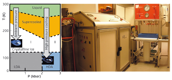
Figure 1. Left side, the phase diagram of water. Unprotected crystals cooled at ambient pressure (AP-cooled) produce crystalline ice. At high pressure, the solvent is transformed into HDA-ice without adding cryoprotectant. Rigth side, the high pressure cooling installation in the laboratory room 30-0-08 (opposite of MASSIF-3).
The HP-cooling method consists of 4 steps schematized in the figure 2: A- Crystal are harvested from crystallization plates, (293K, 1bar). B- Sample loading in the drop tubes, (@ 293K, 200bar). C- Pressurization and cooling of the tubes, (@ 293K, 2000 bar), D-E- Samples HP-cooling, (@ 77K, 2000bar) and Pins/bases assembly under cryo-conditions (@ 77K, 1bar)

Figure 2. The process of high-pressure cooling of macromolecules.
Cryo-HP Tools
We have designed a specific sample support and handling tools. The sample holder is disconnectable and the pin fits inside the tubes of the high pressure setup. The base fits with goniometers and sample changers at the MX beamlines and is SPINE standard (see figure 3).
The crystal is harvested in a spoon shaped capillary and placed at the extremity of the pin, the mother liquor sucked inside the capillary ensures the hydration of the crystal during the whole procedure. We have designed a set of tools to manipulate the pins (a harvesting pen), specific forceps and pliers, and the pins house a ferromagnetic core to be held by a magnet. As can be seen in figure 3, pins are recovered and handled within liquid nitrogen and finally be placed in pucks for diffraction data-collections. The ESRF HP-cooling sample supports are manufactured and commercialised by Mitegen, Ithaca USA.

Figure 3. High pressure tools for handling pins.
Software
The compressor is controled by a software (labview based) on a windows computer (see the figure 4). Once the sample is mounted in the pressure-cell, the target pressure between 200 bar to 2000 bar needs to be entered in the software by pressing the virtual button "compress". Once the pressure is reached, the samples has to be frozen and then the virtual button "decompress" needs being pressed to release the pressure. The sample is then frozen and at ambient pressure and ready to be removed from the cell. Helium is recovered, and the system is able to run additional cycles as shown in the overview figure 4.

Figure 4. Control of the compressor and experiment.
Examples
Figure 5 shows the diffraction patterns of thaumatin crystals. Pannel B, left side shows the diffraction image of an unprotected crystal cryo-cooled at ambient pressure (ice-rings and lost of diffraction power). Pannel B, right side shows the diffraction image of an unprotected crystal treated at high pressure before cryo-cooling. The diffraction to higher resolution as well as a lower mosaicity is clearly visible. Pannel C shows that for a thaumatin, few structural modifications (in red) of the high pressure cryo-cooled crystal can be observed when compared to a classically obtained structure deposited in the pdb. Macromolecular structures from high pressure cryo-cooled structures appear to be relatively isomorphous to those cryo-cooled at ambient pressure and structural changes seem to be limited to a few flexible loops at the proteins surfaces.

Figure 4. High pressure freezing of a thaumatin crystal
High pressure cryo-cooled FAE is an other meaningful example. It reveals that the pressure induces a modification concerning only a single loop at the dimer interface. This simple modification results surprisingly in a superior crystalline quality: a transition to a higher symmetry, a higher resolution obtained, lower B-factors and a lower mosaicity (see the figure 5). Figure 5a highlights the largest structural displacements in red (loop 132). Figure 5b shows the root mean square displacement as a function of residue number of the HP-cooled FEA shows that the structural changes are very small. Figure 5c finally demonstrates that the crystallographic packing of FAE in a surface representation showing the transition from a dimer to a monomer in the asymetric unit due to the increase of symmetry.
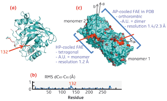
Figure 5. High pressure induced symmetry change within a FAE crystal.
partners


European Synchrotron Radiation Facility - 71, avenue des Martyrs, CS 40220, 38043 Grenoble Cedex 9, France.