- Home
- News
- Spotlight on Science
- Solidification cracking...
Solidification cracking during welding of steel revealed
11-01-2017
Solidification cracking was followed in-situ at beamline ID19 in studies of crack formation during welding of steel.
Welding is the most effective way to join metals permanently; over 50% of global domestic and engineering products are estimated to contain welded joints. In welding, work-pieces are mixed with filler materials and melted, to form a pool of metal that upon solidification becomes a strong, permanent joint. Cracking may occur during solidification of the melt pool, and solidification cracking is an important issue in welding, casting and solidification-related additive manufacturing processes [1]. A sustained deficiency in understanding the fundamental mechanism for damage has driven experimental efforts towards the observation of the phenomenon in situ [2]. In this research, a novel strain-based deformation stage has been developed and installed at beamline ID19. The beamline has a small source size while the divergence and the length of 145 m allows macroscopically-large beam diameters at the position of the experimental hutch. Furthermore, the length of ID19 reduces the effective source size contribution to the images and therefore allows the coherence properties of the beam to be exploited by means of inline X-ray phase contrast.
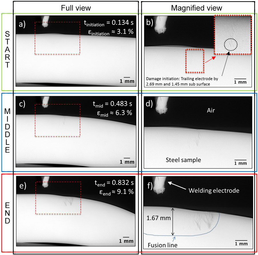
Solidification cracking during welding of steel was observed in situ using high-speed, high-energy radiography. Figure 1 displays a series of processed radiographs. The white tip in the top left of the images is the tungsten welding electrode. The large white part in the centre of the images is the steel test sample. Figure 1a highlights the point at which damage initiation was observed in the radiography sequence. Cracks appear after 0.134 s of bending under a loading rate of 0.135 ms-1. The true strain for damage initiation is 3.1%. Detailed analysis of the damage in Figure 1b reveals that the solidification cracks appear to initiate trailing the welding electrode by 2.69 mm at 1.45 mm sub-surface, approximately 0.22 mm behind the solidification front within the weld.
Upon further loading, the cracks propagate vertically and penetrate the upper surface of the sample after 0.324 s. The velocity of the fracture was measured between 2.2-3.2 x10⁻³ ms-1.
 |
|
Figure 1. Results of in situ radiography analysis, showing: a,b) the initiation of solidification crack at 0.134 s of bending with a true bending strain of 3.1%. Crack initiates trailing the welding electrode by 2.69 mm at 1.45 mm sub-surface; c,d) crack observed at mid-point of test; e,f) the end of solidification cracking at 0.832 s of bending and a true bending strain of 9.1%. |
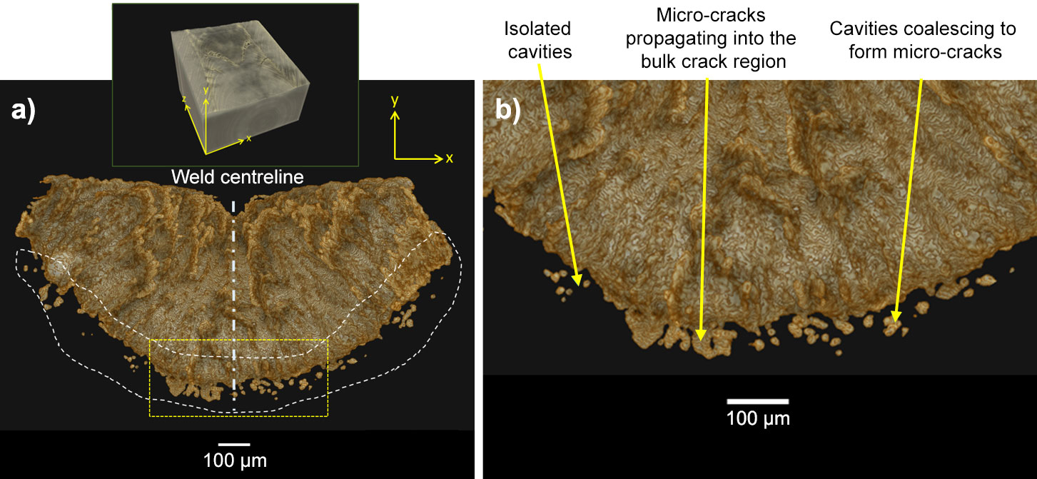
Synchrotron X-ray micro-tomography was used to rebuild and analyse the 3D crack network. The damage initiation sites, observed during the in situ X-ray radiography (Figure 1a and b), are located on the 3D volume reconstructed from X-ray tomographic data and presented in Figure 2. Isolated micro-cavities are situated away from the bulk crack, in the region where damage initiation is observed during in situ radiography. Quantitative analysis of these isolated cavities reveals a size range between 10-27 µm with highly spherical morphologies. In some cases, the micro-cavities coalesce to form isolated micro-cracks, indicating that coalescence is the dominant mechanism for growth in the early stages of damage development.
 |
|
Figure 2. 3D tomographic reconstruction of fracture initiation sites. a) The fracture initiation sites are indicated by a yellow dotted rectangle as observed in the in situ synchrotron X-ray radiography sequence (shown in Figure 1a and b). The region defined by white dashed lines highlight a series of isolated and coalesced microcavities. b) Some of the coalesced microcavities, termed microcracks in the current study, are formed away from the bulk crack region, whereas others have propagated further to join the bulk crack region. |
Damage initiation is dependent upon strain rate. Higher strain rates induce cracking at relatively higher volume fraction of liquid. The true strain required to initiate the damage in this thermodynamic state is higher than for low strain rate due to the increased presence of liquid in the semi-solid skeleton. The extra liquid maintains permeability within the semi-solid skeleton, allowing liquid metal to remain mobile and heal any deformation-induced cavity openings. As a result, the strain required for damage initiation increases.
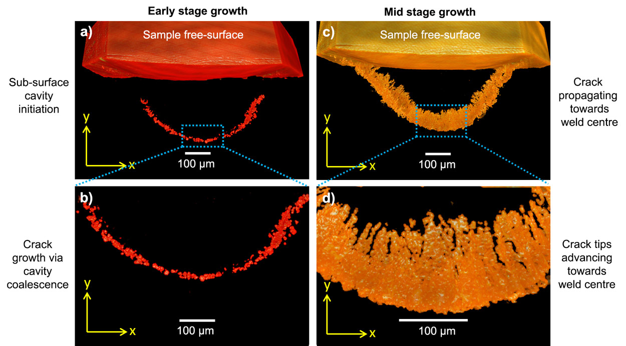
Transverse cross-sectional images at various stages of growth were extracted from the 3D crack network and are presented in Figure 3. The damage grows at a fairly even rate inwards, towards the weld centre and sample free-surface. Closer examination of the crack network reveals several columnar crack tips that advance towards the weld centre.
 |
|
Figure 3. Transverse cross-sectional tomography images showing solidification crack growth path: a,b) Early stage growth; c,d) Mid stage growth. |
Based on the above observation, we propose that solidification cracks grow by linking micro-porosities in the meshing zone in the solidifying weld pool.
Principal publication and authors
Initiation and growth kinetics of solidification cracking during welding of steel, L. Aucott (a), D. Huang (b), H.B. Dong (a), S.W. Wen (a,c), J.A. Marsden (c), A. Rack (d) & A.C.F. Cocks (b), Sci. Rep. 7, 40255 (2017); doi: 10.1038/srep40255.
(a) University of Leicester (UK)
(b) Oxford University (UK)
(c) Tata Steel, Research & Development, Rotherham (UK)
(d) ESRF
References
[1] M. Tong et al., JOM 65, 99-106 (2013).
[2] L. Aucott, PhD Thesis, University of Leicester (2015).
partners


European Synchrotron Radiation Facility - 71, avenue des Martyrs, CS 40220, 38043 Grenoble Cedex 9, France.