- Home
- Users & Science
- Find a beamline
- ID13 - Microfocus Beamline
- Beamline layout
Beamline layout
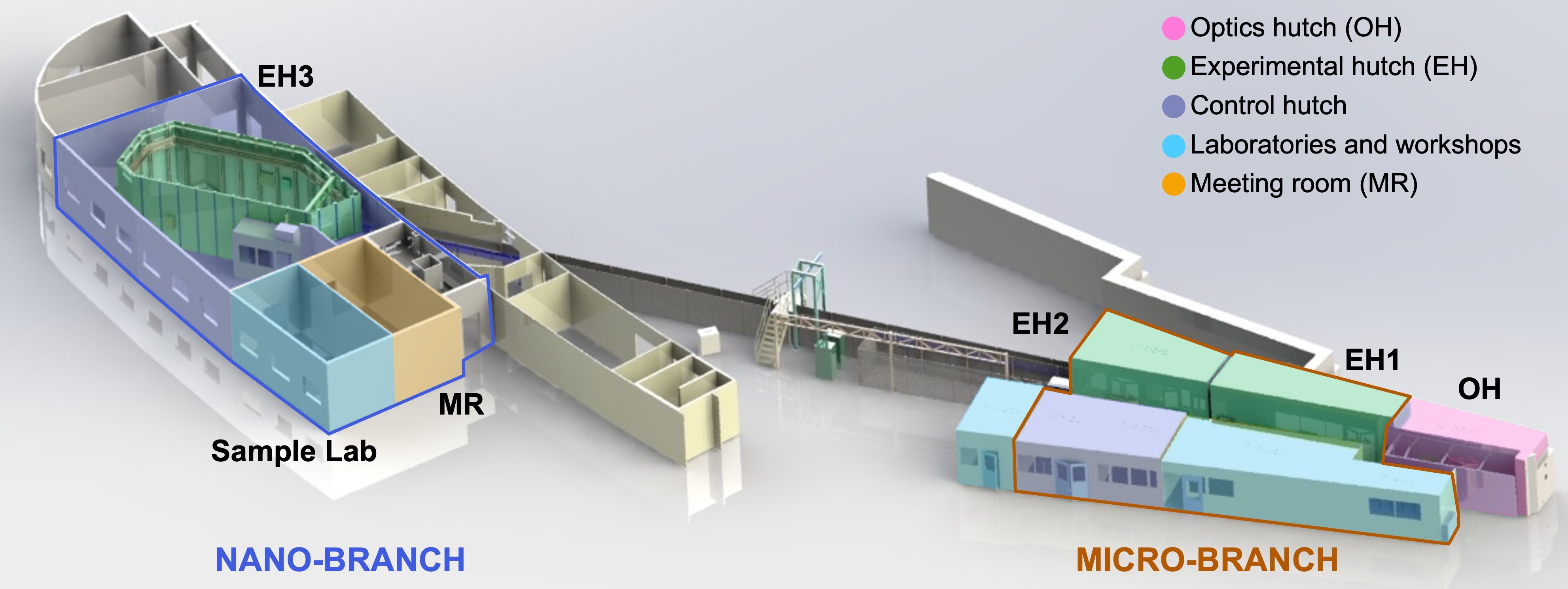
The beamline ID13 is located in the main experimental hall, Sector 14-5. The beamline has two end stations that offer two distinct beam sizes: the micro-branch, and the nano-branch, each with a dedicated control room. At the beamline premises, there are two wet chemical labs, sample preparation facilities equipped with microscopes and sample handling tools, and a meeting room with tea and coffee available for the users.

Micro-branch (EH2)
The microfocus end-station (EH2) is dedicated to experiments requiring focused beam size from 20 µm down to 2 µm. Placed 46 m away from the source, it allows a maximum distance between the sample and detector up to ~2 m.
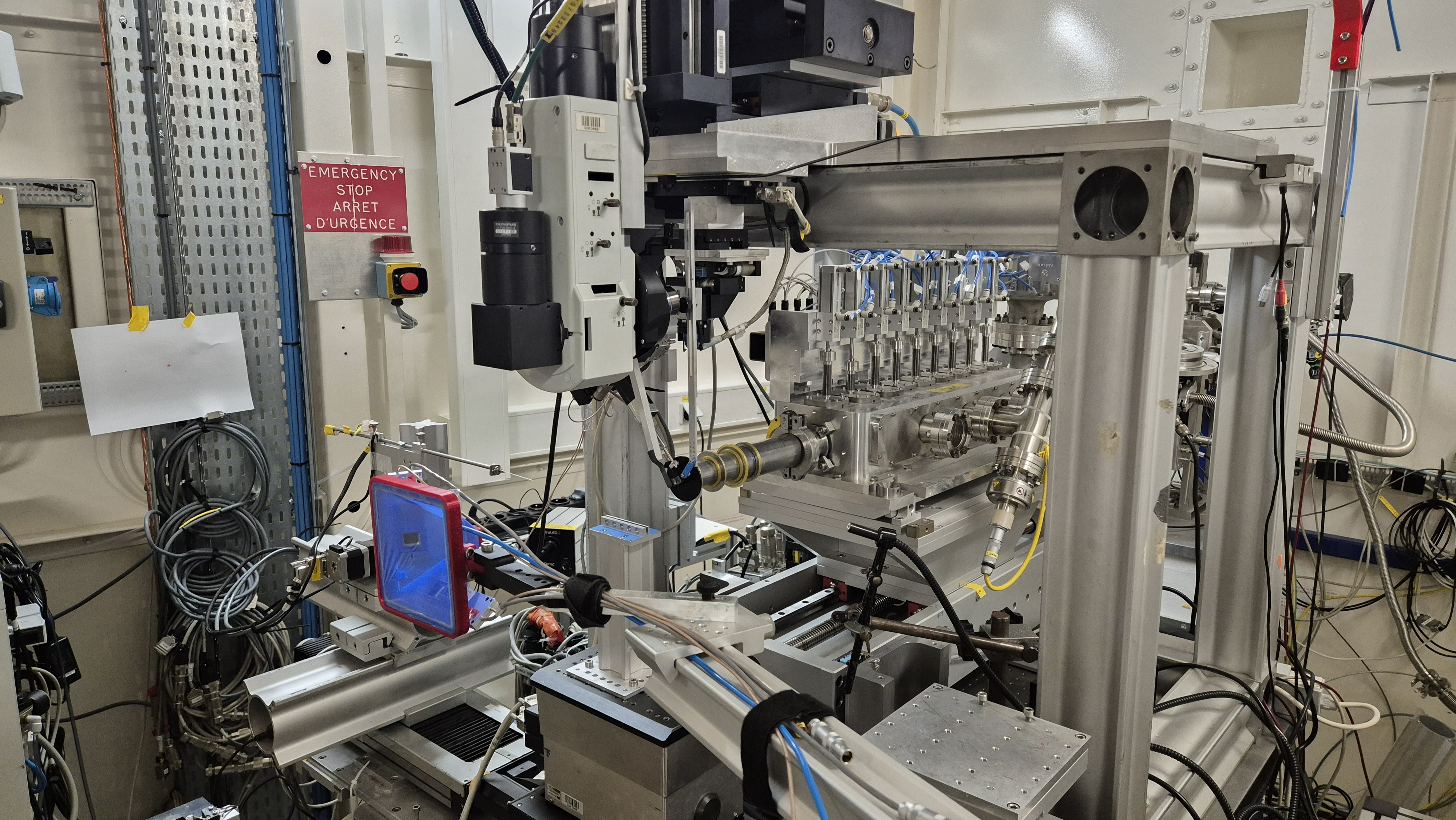
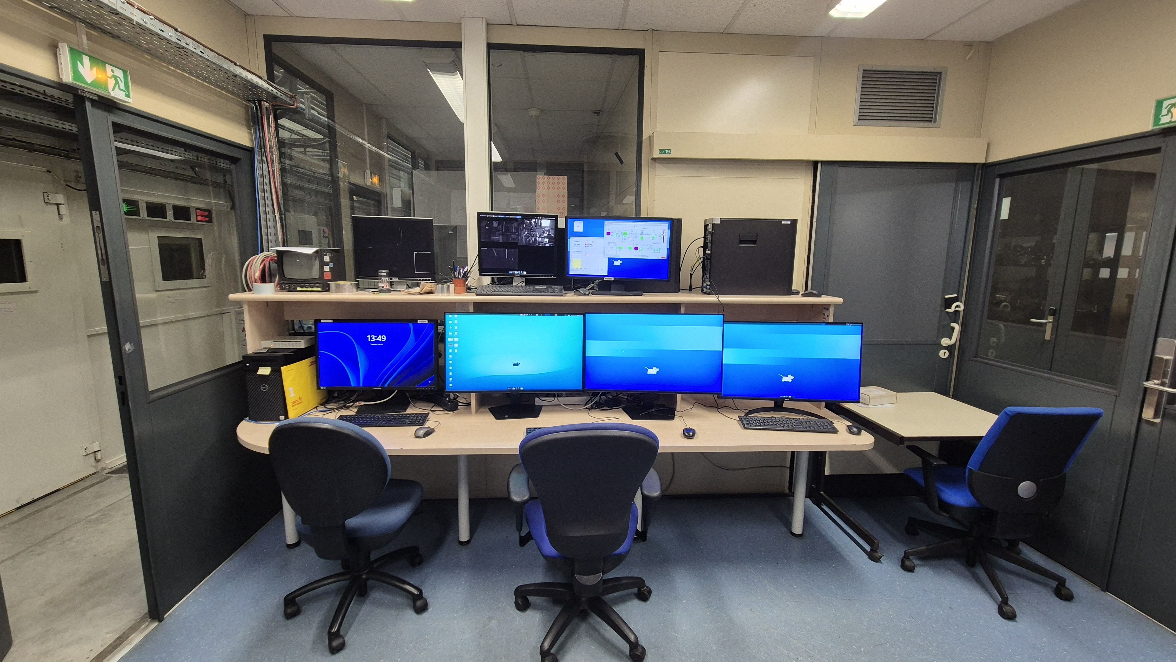
Micro-branch experimental hutch (EH2) Micro-branch control room
The micro-branch is composed of the following elements (detailed information in the Technical information page):
-
A set of tungsten slits, positioned upstream of the focusing optics, are used to cut in the monochromatic beam to adjust its size and position on the focusing lenses.
-
The micro-beam is achieved using parabolic Be Compound Refractive Lenses (CRLs) in a transfocator mounted on an hexapod for precise alignment of the optical axis.
-
An ionization chamber is positioned upstream the sample to measure the incoming beam intensity (I0).
-
An aperture downstream is used to obtain a clean the beam without unwanted background scattering and diffusion.
-
The sample can be raster scanned using stepper motors in the two axes perpendicular to the beam direction. A rotational stage can be integrated on top of the scanning stages for angular-dependent measurements, tomography, or diffraction experiments requiring sample rotation.
-
A flight-tube filled with He gas can be added downstream the sample to reduce the air absorption and minimize background. The flight-tube can be equipped with photo-diodes to measure the back-scattered radiation and quantify the transmitted intensity (I).
-
The directly transmitted beam is blocked by a lead beam-stop mounted on a glass needle. The beam-stop size can vary from 100 µm to 3 mm in thickness depending on the required conditions.
-
Different detectors can be placed at the back of the end-station depending on the technique used (SAXS, WAXS, XRF, ptychography...). The detectors can be positioned at varying distances up to ~ 2 m.
-
An additional fluorescence detector can be placed laterally to acquire the X-ray fluorescence signal from the sample.
Nano-branch (EH3)
The nanofocus end-station is dedicated to experiments requiring focused beam size from 500 nm down to 50 nm. Placed 98 m away from the source, it allows a maximum distance between the sample and detector up to ~3 m.
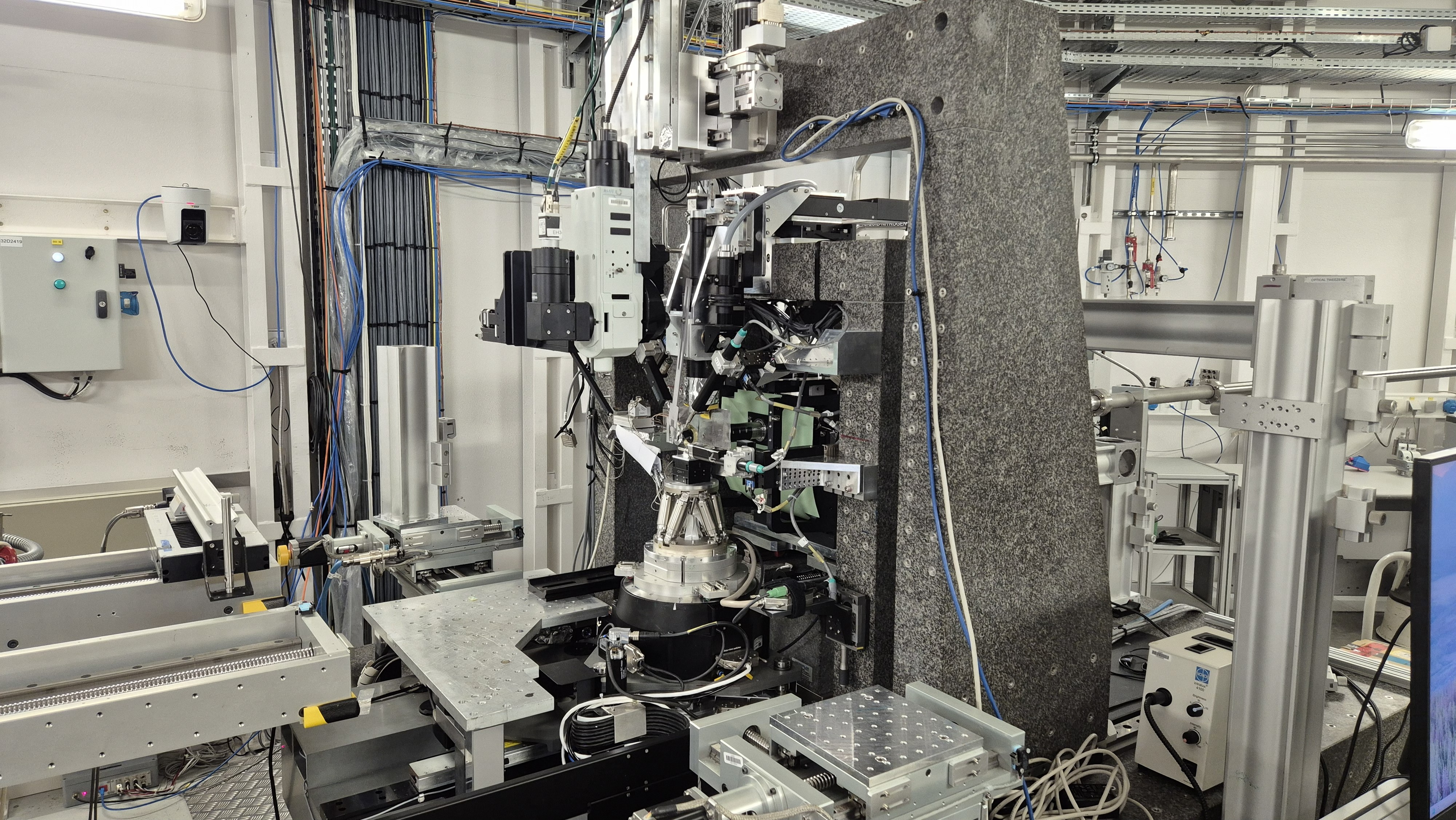
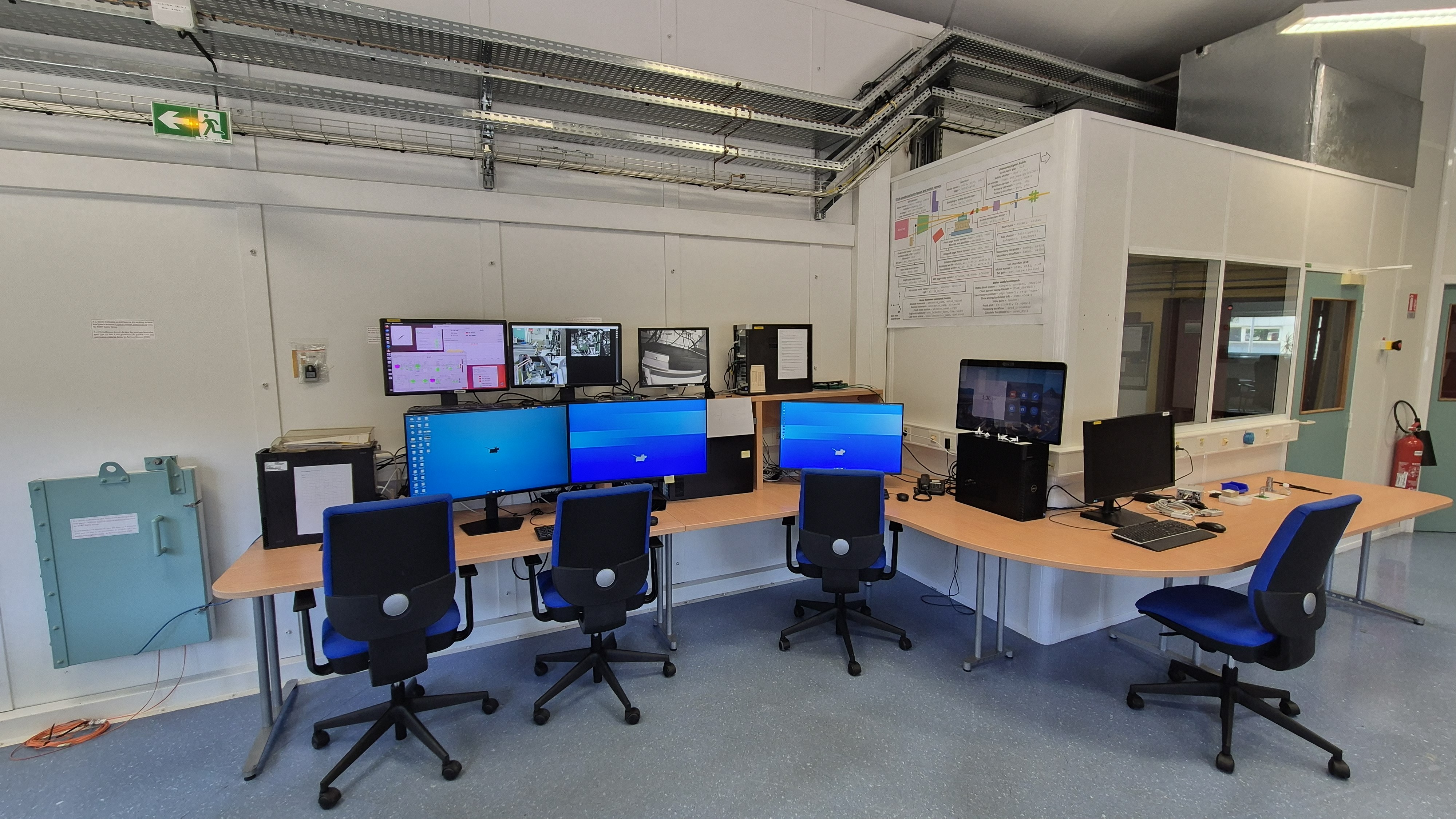
Nano-branch experimental hutch (EH3) Nano-branch control room
The nano-branch is composed of the following elements (detailed information in the Technical information page):
-
A set of tungsten slits, positioned upstream of the focusing optics, are used to cut in the monochromatic beam to adjust its size and position on the focusing lenses.
-
The nanobeam is achieved using multilayers Laue Lenses (MLLs) of different focal length. MLLs are chromatic optics and their focusing capabilities depend on the X-ray energy.
-
An ionization chamber is positioned upstream the sample to measure the incoming beam intensity (I0).
-
A 40 µm Platinum-Iridium square order separation aperture (OSA) is used to suppress unwanted diffraction orders coming from the diffractive lenses.
-
A hexapod stage provides high-precision alignment for accurate positioning of samples and sample environments. The sample can be raster scanned using piezo-motors. A rotational stage can be integrated on top of the scanning stages for angular-dependent measurements, tomography, or diffraction experiments requiring sample rotation.
-
A flight-tube filled with He gas can be added downstream the sample to reduce the air absorption and minimize background. The flight-tube can be equipped with photo-diodes to measure the back-scattered radiation and quantify the transmitted intensity (I).
-
The directly transmitted beam is blocked by a lead beam-stop mounted on a glass needle. The beam-stop size can vary from 100 µm to 500 µm in thickness depending on the required conditions.
-
Different detectors can be placed at the back of the end-station depending on the technique used (SAXS, WAXS, XRF, ptychography...). The detectors can be positioned at varying distances up to ~ 3 m.
-
An additional fluorescence detector can be placed laterally to acquire the X-ray fluorescence signal from the sample.
Laboratory and sample preparation facilities
Wet chemical lab
Wet chemical labs can be found at the micro- and the nano-branch.
Equipment:
- Fume hood for chemicals in each wet lab
- Basic chemicals: isopropanol, acetone, ethanol, distilled and ultrapure water
- Vacuum oven (microbranch)
- Desiccator (nanobranch)
- Two PalmSens4 Potentiostats (nanobranch)
- There is an electrochemistry lab with gloveboxes (preliminary request during your proposal submission required)
Sample preparation
- Flaming-Brown micro-tip puller to manufacture glass needles (nanobranch)
- Sample fridge (microbranch)
- Optical microscope with digital camera (nanobranch)
- Two optical stereo microscopes (nanobranch)
More information can be found on the Samples and environments page.
partners


European Synchrotron Radiation Facility - 71, avenue des Martyrs, CS 40220, 38043 Grenoble Cedex 9, France.