- Home
- Users & Science
- Find a beamline
- ID22 - High resolution powder diffraction beamline
- Technical Description
Technical Description
Here you find information on ID22's
- X-ray source,
- Optics (including monochromator and transfocator)
- Experimental hutch (standard- and strain-scanning diffractometers, multianalyser stage and 2D-detector)
- Laboratory facilities
X-ray Source
The beamline has as source a 2.5 m long in-vacuum u26 undulator, with a minimum gap of 6 mm. It can cover the energy range from 6 keV to around 75 keV (2.07 Å. to 0.17 Å in wavelength) with high photon flux at both low and high energies.
(top)
Optics Hutch
Powder diffraction is a technique that requires a relatively large beam to illuminate a sufficient volume of sample so as to give a good powder average. In high-resolution experiments, there is no focussing; the highly collimated beam from the source is simply monochromated and passes unperturbed to the sample. A transfocator can be used when using the Perkin Elmer medical imaging detector for improved angular resolution or, if higher spatial resolution is required, at the sample.
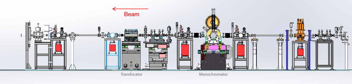
Figure 1: The outline of the ID22 optics hutch.
(top)
Monochromator
The beam is monochromated by a cryogenically-cooled channel cut Si 111 monochromator, with an overall length of 300 mm and a distance of 4 mm between the two diffracting surfaces. The second surface can be fine-tuned to match the X-rays transmitted by the first surface. The first block of the monochromator crystal, which receives the highest heat load, is side cooled to about 105 K by copper blocks through which liquid nitrogen flows. Water-cooled slits define the size of the beam incident on the monochromator, and of the monochromatic beam transmitted to the sample, typically in the range 0.5 – 1 mm (horizontal) by 0.1 – 1 mm (vertical), as required.
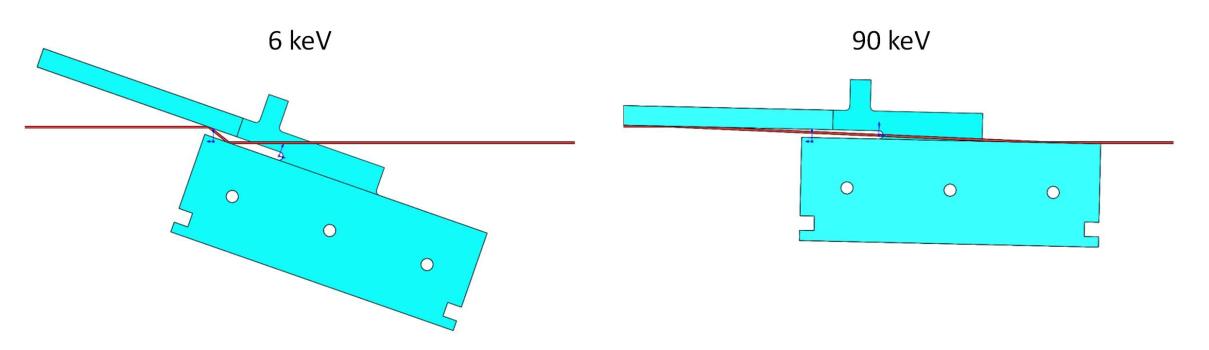
Figure 2: Drawing of the channel cut crystal installed on ID22, showing the beam path at 6 keV and 90 keV.
(top)
Transfocator
A transfocator, using parabolic cylindrical Al lenses produced by the ESRF, is also available.
For strain-mapping experiments, the beam can be focussed to around 50 µm to improve spatial resolution. Strain scanning also benefits from the high-energy performance, permitting the investigation of thicker components and those made of highly absorbing materials such as steel and nickel. It is also be possible to combine a focussed beam of energy 70 keV with an area detector to allow the use of the "fast-PDF" technique, complementing the "quality-PDF" obtained by (slower) scanning of the multi-analyzer stage.
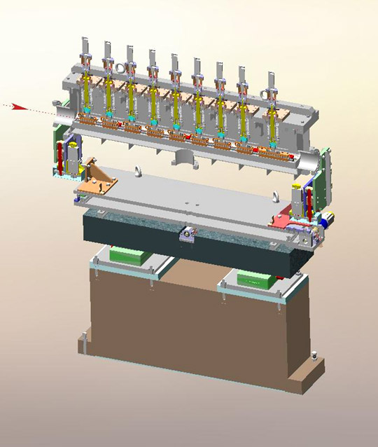
Figure 3: Drawing of the transfocator on ID22.
(top)
Experimental Hutch
Diffractometer
ID22's two-circle diffractometer was manufactured by LAB systems (Leuven). It is of heavy-duty construction, exploiting air bearings for each axis, and is mechanically stable, accurate (nominally ±1 arcsec) and precise (sensitive to displacements of 5x10⁻⁵°). It can accept spinning capillary or flat plate specimens. In routine high-resolution operation, a multi-analyzer stage comprising thirteen Si 111 crystals (each separated from its neighbour by approximately 2°) is scanned with the transmitted signals recorded by a Dectris Eiger2 X 2M-W CdTe pixel detector. Multiple crystals operating in parallel increase the efficiency of detecting the diffracted radiation, and for dynamic measurements means that the detector arm needs to be scanned by no more than about 2.3° to measure an angular range of 26° in 2θ. The use of a pixel detector behind the multi-analyzer stage allows the effects of axial divergence to be compensated, leading to improved peak shape, angular resolution, and overall statistical quality.
For crystallographic studies, the use of a spinning capillary reduces preferred-orientation effects for all but needle-like samples that can align with the capillary axis. With the energy range available, the energy and capillary diameter can be selected to minimise absorption even for samples containing heavy elements. Hence the diffracted intensities can also be very accurate. Indeed, even in cases where a highly absorbing sample is unavoidable, such as when working at the absorption edge of an element in the sample, we would usually prefer to stick a fine layer of sample to the outside of a 1-mm-diameter glass capillary with silicone grease, rather than use a flat plate.
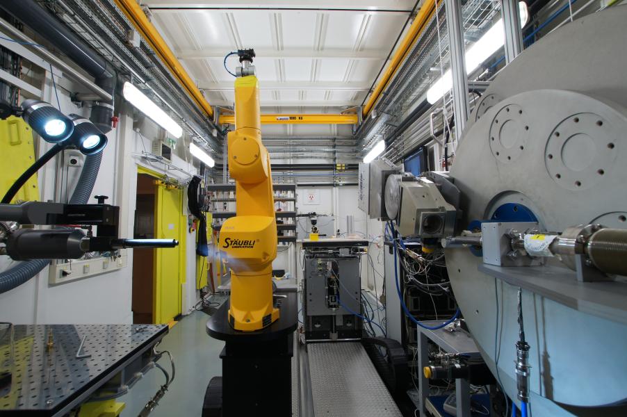
Figure 4: The ID22 powder diffractometer (right), with the sample changing robot (middle) and the cryostream (left).
(top)
Multianalyser stage
The thirteen analyzer crystals are mounted on a single rotation stage, so only a single adjustment of the Bragg angle is needed when changing the wavelength. The original multianalyser stage, shown in figure 5 [1] was conceived by the Laboratoire de Cristallographie at the CNRS, Grenoble, and produced as part of the collaboration that supported the construction of ESRF's first high resolution powder diffraction beamline, BM16.
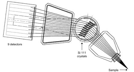
Figure 5: Schematic drawing of the multianalyser stage [1].
A diffracted X-ray must strike an analyser crystal at the correct angle to be diffracted into the detector. Since the acceptance of a Si 111 crystal is very small (a few arcsec, depending on energy), an analyzer crystal stringently defines the 2θ angle of diffraction. Since the analyzer determines a true angle of diffraction, (rather than inferring the angle from the position of a slit or a pixel on a position-sensitive detector), the use of an analyzer crystal renders the positions of diffraction peaks immune to displacement-type aberrations, such as specimen transparency and modest misalignment of the sample with respect to the axis of the diffractometer, that affect conventional arrangements with a scanning slit or a PSD.
Mechanically and optically having the exact nominal offset between channels is not critical. However, to combine the data from different channels, the offsets need to be known accurately and are obtained by comparing those parts of the diffraction pattern measured by all of the channels. The offsets and channel efficiencies are then computed so that the signals superimpose as closely as possible [2]. A sample such as Si standard NIST 640c is usually used for this calibration step which is performed regularly, and whenever the wavelength is changed. With the excellent mechanical integrity of the diffractometer and the high collimation of the beam, the peaks are very narrow, with an instrumental contribution to the FWHM of around 0.0025° 2θ, and their positions are accurate and reproducible to a few tenths of a millidegree. Narrow peaks and accuracy in the peak positions are essential for high quality powder diffraction measurements. Since for flat-plate samples there is no need to be in the θ/2θ condition for narrow peaks, (there being no parafocussing condition to fulfill), the analyzer crystals also offer advantages for diffraction at grazing- incidence, and for reflectivity.
(top)
2D detector
The flat panel Perkin Elmer XRD 1611CP3 (figure 6) is available as a complementary detector for total scattering measurements at high energies.
The XRD 1611 consists of a 41 × 41 cm2 CsI scintillator bonded to an amorphous silicon substrate. The detector has a pixel size of 100 × 100 µm2 and potentially a maximum readout speed of 3.75 frames per second at maximum resolution. Installed on a motorized linear translation stage (Figure 6) that allows variation of the sample-detector distance between 2500 and 380 mm, it can be used to attain a maximum momentum transfer in one shot (Qmax) of 29 Å-1 at 70 keV).
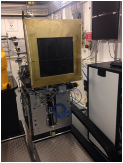
Figure 6: The Perkin Elmer XRD 1611 detector mounted on its motorized translation stage
Laboratory Space
The ID22 sample preparation laboratory is located in front of the beamline (room 21.0.04a), towards the outside of the ring. It provides the ID22 users with space, tools and supplies to prepare and mount sample capillaries.
You will also find:
- standard laboratory items (tweezers, spatulas, scalpels, gloves, goggles, pipettes, syringes, needles, ...)
- a balance
- a drying oven and a fridge for chemicals
- a centrifuge for capillaries (e.g. sedimentation of precipitates)
- an optical microscope
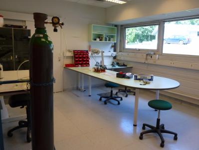
Figure 7: The sample preparation laboratory at ID22.
If you want to use the ESRF support laboratories, you have to book them in advance via the A-Form. For access to the chemistry laboratory, fill in the user declaration form (.doc)(.pdf) and return it to the user office at least 15 days before the starting date of the experiment.
(top)
References:
[1] Nine crystal multi-analyser stage for high-resolution powder diffraction between 6 and 40 keV. J.-L. Hodeau, P. Bordet, M. Anne, A. Prat, A. N. Fitch, E. Dooryhee, G. Vaughan, and A. Freund, Proc. SPIE, 3448, 353 (1998).
[2] Merging data from a multi-detector continuous scanning powder diffraction system. J. P. Wright, G. B. M. Vaughan, and A. N. Fitch, IUCr Computing Commission Newsletter, 1, 92 (2003).
[3] ID22 – the high-resolution powder-diffraction beamline at ESRF. A. N. Fitch et al. J. Synchrotron Rad. (2023). 30, 1003–1012 https://doi.org/10.1107/S1600577523004915
partners


European Synchrotron Radiation Facility - 71, avenue des Martyrs, CS 40220, 38043 Grenoble Cedex 9, France.