- Home
- ID03 - Users Guide
- Beamline Description
- ID03 - Filters
ID03 - Filters
The nice thing : the automatic operation of the filters:
The three modes of operations of the filters :
Procedure for starting to use the filters under SPEC
Additional information : macros, config
Cabling of the filter system :
3) On the VME’s (racks in the corridor between ID3 and the next beamline)
Filters on ID3.
General setup
The box of remotely operated filters is located between the monitor and the sample.
Three filter boxes are available, each with a different foil material :
- Aluminum foils, 0.2 mm thickness (good for 10 KeV)
- Aluminum foils, 0.5 mm (good for 12-14 KeV)
- Molybdenum foils, 0.025 mm (good for 17 KeV)
One has to adapt the filters material to the energy of the x-ray beam. A good rule of thumb is to have one foil attenuate the intensity by a factor of 1.5 to 2.5 for the energy considered.
Due to the not-so-easy mounting and un-mounting of the foils in the filters box, it is recommended to have several filters box available. (one could also try to make the filters boxes more user-friendly but that remains to be done).
Each box contains 4 filters that can be put in series with each other :
- filter 1 : 1 foil
- filter 2 : 2 foils
- filter 3 : 4 foils
- filter 4 : 8 foils
Using a binary combination of the 4 filters, one has the choice between 16 different levels of attenuation (0 to 15 foils in the beam).
The nice thing : the automatic operation of the filters:
This option, available under SPEC, allows to have an electronics automatically insert or remove the filters depending on the number of counts that arrives on the detector. The electronics, developed by J. Alvarez and E. Paiser, measures the dead-time of the detector and insert filters in the incident beam until the dead-time is back under a certain threshold (the dead-time is a measurement of how saturated the detector is).
The three modes of operations of the filters :
Mode (1) :
directly from the rack, by moving the switches of the XIA card manually. In this case one has to note in the logbook how many filters are used (this is not really convenient).
Mode (2) :
manually under SPEC, using the command :
filteroff
and the commands :
filterset 0 (no filter)
filterset 1 (1 foil)
…..
filterset 15 (15 foils, maximum attenuation)
where ''filterset n'' puts n filter foils in the beam by a combination of the 4 available filters.
In this mode (and also in mode 3)), when you do a ''ct'' (count), SPEC tells you by a number between 0 and 15 how many attenuator foils are present, and the counter ''det_corr'' provides the corrected intensity, that is :
IREAL = I MEASURED x (attenuation factor of one foil) NUMBER OF ATTENUATOR FOILS
During a scan, at each point of the scan, the number of attenuator foils present, the value of det_corr, and the value of Detector, are stored as columns in the SPEC file. This way, you don't need to note in the logbook how many filters you have put.
Mode (3) :
automatically under SPEC using the command :
filteron
Then the program automatically sets the correct number of filters in the beam to avoid the saturation of the detector.
Note that in the case of very intense beams, like the direct beam, the maximum number of filters may not be enough to prevent the detector from saturating, and you will have to reduce the slits anyway. This is particularly true with aluminum filters, which have a low attenuation.
Another problem that we had is the following : if you stay on a Bragg peak and close the shutter, the system removes the filters. When you open again the shutter, the detector can be so saturated that the measurement of the dead-time will be completely wrong, and the electronics will not put ANY filters into the beam. This is an easy way to kill a detector (ours took 10-15 min to recover when this happened : it had seen so many counts that it was always seeing counts with the shutter closed). So if you close the shutter while you are on a Bragg peak, do a filteroff and a filterset 15 before you re-open the shutter : that’s safer.
Mode (3) is particularly useful when you do a L-scan on a Crystal Truncation Rod : you can measure both the low intensity part of the rod and the Bragg peaks in the same scan. It is also very useful for reflectivity scans.
For alignments, mode (3) makes SPEC a bit slower but reduces the hassle of changing the attenuators by hand. Typically, a counting time of 0.1 s is too small for the attenuators to follow correctly. A safe counting time is 0.5 s.
Procedure for starting to use the filters under SPEC
This procedure is to be used as a “reset” procedure of the electronics when something has gone wrong, or simply when starting to use the system. One possible improvement of the electronics would be to replace this procedure by a reset button.
- make sure everything is connected correctly (see below)
- put the 4 filter switches on the XIA card toward the left (red lights OFF, filters extracted)
- filteroff (in SPEC)
- unplug the attenuator card (the gold one) by extracting it by 1 cm from the rack
- unplug the upper 9-pin connector then replug it
- replug the attenuator card
- shclose (in SPEC) (closes the beam shutter)
- det_cal (in SPEC) This command should return values like :
00.084 4.5290.101
if it returns only zeros, try doing the “det_cal” command again and again.
- shopen (in SPEC) (opens the beam shutter)
- ct (in SPEC) (counts 1 second)
After this procedure, if you do a “filterset 1” in SPEC, the red light corresponding to filter 1 should come ON on the XIA filters card, and the “ct” command in SPEC should return “Attenuator = 1”.
For calculating Det_corr, one then needs to enter the attenuation factor into SPEC.
For the automatic insertion of filters, one needs to setup the thresholds on the dead-time for inserting or removing the filters.
Here is the procedure to determine the thresholds (and also the attenuation factor) :
- put the diffractometer in a position where the detector is not saturated but the dead-time is large enough (typically 0.05). This should correspond to an intensity of about 55000 cts/s in EH1 (SIXCV) and about 30000 cts/s in EH2 (SIXC).
- filterset 0
- ct
this gives for example : detector = 31000 cts/s
dead-time = 0.045
- filterset 1
- ct
this gives for example : detector = 14900 cts/s
dead-time = 0.017
- filtersetup
this asks you first :
Threshold to insert filters (....) ?
Here you put a value slightly higher than the dead-time you measured with zero filters (for example 0.05).
Then it asks you :
Threshold to extract filters (....) ?
Here you put a value slightly smaller than the dead-time you measured with one filter (for example 0.015)
It then asks you :
Attenuation factor (...) ?
Here you put the ratio between the counts you measured with zero filter and with one filter (here 2.08 = 31000 / 14900)
and finally it asks for :
Serial line number in config (...) ?
Here you put :
id3/ser032_1/15
if you are working in EH1 (SIXCV) and :
id3/ser032_1/13
if you are working in EH2 (SIXC).
Note that you have to change the thresholds and attenuation factor each time you change the energy of the x-rays, the type of filters (moly, aluminum ...), or the type of detector (thresholds adjusted in EH1 may not work in EH2 because the detector is different).
Typical settings : at 17.14 KeV
- for SIXC (EH2), with molybdenum 0.2 mm filters :
filtersetup0.050.0152.71id3/ser032_1/13
- for SIXCV (EH1), with aluminum 0.5 mm filters :
filtersetup0.060.0252.04id3/ser032_1/15
After doing that if you type :
- filteron
and you go to an intense peak, SPEC should start inserting filters automatically as soon as the dead-time is larger than 0.05.
To go back to the manual mode you have to type :
- filteroff
What is the logic behind this procedure with the thresholds :
Imagine that you want the dead-time to stay under 0.06. So the electronics has to add one filter when the dead-time is above 0.06. But it also has to remove the filters when the dead-time becomes too low (that is : if by removing a filter one gets a dead-time that is smaller than 0.06, the system should remove at least one filter). So you would put the upper threshold at 0.06. The question is then : how much do I put for the lower threshold ? Basically, you have to estimate by how much you reduce the dead-time when you add a filter, being originally with a dead time of 0.06. So you go to a place where the dead-time is around 0.06, you add a filter, and you measure the new dead-time (for example 0.02). The first idea would then be to put 0.06 for the upper threshold and 0.02 for the lower. But if you put exactly those values, when you go to a point with a dead-time of 0.065, the system will add a filter, but then the new dead-time will be slightly above 0.02, so the system will remove again the filter it just added, and this will go on forever : the system will not be able to decide if it should insert or not the new filter. That’s why the distance between the two thresholds has to be slightly larger than the measured interval : in the case taken here, one would typically choose 0.065 for the upper threshold and 0.015 for the lower threshold.
What could be improved :
In the method given above, the attenuation factor is measured only for one foil (filter 1). One could object that the different foils could have slightly different attenuation factors, if their thickness varies a bit from foil to foil for example, or if a foil is damaged etc... It would then be more correct to measure separately the attenuation factors of the 4 filters. This is not so easy for filter number 4, which has typically an attenuation factor of 28 = 256.
Also, in the method given above, the attenuation factor is measured with a non negligible dead-time of the detector. One could object that the measurement is not accurate, since for accurate intensity measurements, the detector should always be in the linear region, with zero dead-time. There are two ways to get around the problem : First, one can do the two intensity measurements (with and without filter 1) in a region where the intensity is low enough to have almost zero dead-time. However, this requires to count longer to have a good statistics on the intensity measurement done with filter 1 in the beam. If one wants in addition to measure the 4 attenuation factors of the 4 filters separately, it is clear that there will be a big problem with filter 4 : if the detector is in the linear regime without filter, the intensity will be reduced to almost nothing when filter 4 is in the beam. The second method, to get more accurate measurements of the intensity, is to compensate for the dead-time in the measured intensity : for example, if one measures 30000 cts/s and a dead-time of 0.06, the real intensity is (1/ 0.94) times 30000 cts/s, i.e. 31915 cts/s. Of course, for doing this you need to be sure that the dead-time measured by the detector electronics is reliable : for heavy saturation of the detector, the dead-time is no more reliable.
The “blmenu” command :
All the commands described up to here work in SIXC as well as in SIXCV. In SIXC (EH2) there is another command called “
blmenu” that enables you to do everything that is done by the commands “
filteron /
filteroff”, “
detcoron/
detcoroff” and “
filtersetup”, without having to remember the names of the individual commands (which is nice).
Before using blmenu, make sure that no filter is in the beam.
If you type the command :
blmenu (in SPEC)
then a menu appears that looks like :
01 FiltersOff(or On)
02Detection correctionOn(or Off)
03MagnetOn(or Off)
04Magnet in scans Off(or On)
Enter number to change, e for extra, or 0 to exit (0) ?
Entering the number “1” enables you to switch to filters ON or OFF. This is equivalent to executing the commands filteron or filteroff.
Entering the number “2” enables you to switch the detection correction ON or OFF. This is equivalent to executing the commands detcoron and detcoroff (see section “Troubleshooting” for the definition of these commands).
Entering the letter “e” leads you to a second menu that looks like :
01Detcor setup
02Magscan setup
Enter option number or 0 to return to main (0) ?
Entering the number “1” leads you to a menu that is exactly the same as the one you get by executing the command “filtersetup”.
In SIXCV (EH1), there is also a blmenu command but it is limited to duplicating the filteroff / filteron commands.
Troubleshooting
Here is a non-exhaustive list of problems already encountered :
First problem :
SPEC returns “Attenuator = 0” although one or several filters 1 are in the beam.
To solve this problem, you have to use the commands :
- filterset 0 (in SPEC)
- detcoron (in SPEC)
In the “detcoron” mode, each time you do a “ct”, SPEC will :
1) read from the XIA filters box the number of filters that are in the beam
2) calculate the value of Det_corr which depends on the measured intensity, the number of filters, and the attenuation factor given in “filtersetup”.
The inverse command :
detcoroff (in SPEC)
disables the reading by SPEC of the status of the XIA filters box. This can be useful in case of serious serial line problems, if you want to get rid of the filters control via SPEC and come back to the good old manual mode (with the switches).
Note that for avoiding serial line errors, the detcoron / detcoroff commands should be used only with zero filter in the beam.
Second problem :
Sometimes when you do a “filterset n” or a “ct” you get an error message such as :
Serial line error ....
Error on reading string on device (75) ....
One possible cause for this problem is a mechanical problem in the filters box : the controller is trying to insert a filter and is not able to do it, so it tries again and again, and while it is doing that it can not answer the questions from SPEC, so SPEC returns a serial line error.
Such a situation can be detected by the fact that, on the XIA card, one of the 4 red lights is slightly blinking. To solve this problem, one can try to operate back and forth the switch corresponding to the blinking light (to “unstick” the filter). The switch should be put back to the left before using again filterset in SPEC.
Additional information : macros, config
For using the options where the filters are operated through SPEC, one has to load the filters macro into SPEC using the command :
qdo /users/specadm/jmacros/detcor.mac or simplyjdo detcor.mac
This is normally done automatically when starting SIXCV or SIXC.
Here is how the config should look like when using the filters :
When you type “config” then “c” you should see something like :
- in sixcv (EH1):
|
SERIAL
|
DEVICE
|
TYPE
|
BAUD
|
MODE
|
|
0 YES
|
id3/ser032_1/15
|
ESRF
|
9600
|
raw
|
- in sixc (EH2):
|
SERIAL
|
DEVICE
|
TYPE
|
BAUD
|
MODE
|
|
0 YES
|
id3/ser032_1/13
|
ESRF
|
9600
|
raw
|
then you exit the config by typing “Ctrl+C”.
Here is another way (other than det_cal) of checking that the communication with the serial line is working : under SPEC, you type :
p ser_put(0,”?\r\n”) ; p ser_get(0)
If everything works, SPEC should return :
....... (to be completed)
A macro has been developed to test the filters during a long time (to track the problem of serial line errors that was appearing with VME ID031 and that is apparently solved by using VME ID032) :
The macro name is :
filtertest (in SPEC)
To use this macro you have to do :
qdo /users/opid03/data/Jan00/ftest.mac (in SPEC)
This launches Ernesto’s version of filtertest, which is the latest one. Take care of the possible confusion with the older version of filtertest present in detcor.mac.
Cabling of the filter system :
1) In the control room
Below is a schematic drawing of the filters electronics as it looks in the rack in the control room (on the
front side).
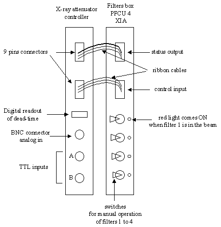
For Experimental Hutch 1 (EH1) :
The corresponding filters cards are in the lower rack. One needs to connect the SIGNAL OUT output of the detector electronics (CYBERSTAR card on the same rack) to the ANALOG IN input in front of the “x-ray attenuator controller” card.
For Experimental Hutch 2 (EH2) :
The corresponding filters cards are in the upper rack. One needs to connect the BNC cable from the AMP output of the detector electronics (ORTEC 590 A card on the same rack) to the ANALOG IN input in front of the “x-ray attenuator controller” card.
Below is a schematic drawing of the back of the “x-ray attenuator controller” card and the PFCU-4 XIA card .
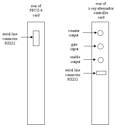
Connections at the rear of the two cards :
For EH1 (upper cards) :
- x-ray attenuator controller card :
|
port
|
cable to be connected to this port
|
|
COUNTER OUTPUT
|
nothing
|
|
ENABLE OUTPUT
|
BNC cable
label :VME ID032 VCT6 gate out 1 NIM ID032 XR ATT CTRL gate in |
|
GATE INPUT
|
BNC cable
label : VME ID032 VCT6 gate in 1&2 NIM ID032 XR ATT CTRL gate out |
|
RS232
|
serial line cable
label : ID03 / S 25 B |
- PFCU-4 card :
The serial line port (DB9) is connected to the cable labeled : XIA PF CAB 25 (white sticker)
For EH2 (lower card) :
- x-ray attenuator controller card :
|
port
|
cable to be connected to this port
|
|
COUNTER OUTPUT
|
nothing
|
|
ENABLE OUTPUT
|
BNC cable
label :VME ID031 VCT6 gate out 1 NIM ID031 XR ATT CTRL gate in |
|
GATE INPUT
|
BNC cable
label : VME ID032 VCT6 gate in 1&2 NIM ID032 XR ATT CTRL gate out |
|
RS232
|
serial line cable
label : ID03 / S 15 B |
- PFCU-4 card :
The serial line port (DB9) is connected to the cable labeled : EXC-8719-A (yellow plastic label)
2) In the experimental hutch
The filters box is located on the extremity of the entrance rail closest to the sample. It has a DB9 connector on top where we plug the serial line cable coming from the PFCU-4 XIA card (located in the control hutch). There is also a blue plastic pipe connected to an inlet on the side of the box, that bring the compressed air necessary to operate the filters. On top of the box, there are also 4 red lights (one for each filter), that come ON when the corresponding filter is inserted (i.e. in the path of the x-ray beam).
(is there also a power cable ?)
The serial line cable to plug on top of the box is labeled :
- “EH2” in EH2 (dark gray cable, label marked with a pen directly on the cable)
- “EXC-8719-B” in EH1 (light gray cable, yellow plastic label)
3) On the VME’s (racks in the corridor between ID3 and the next beamline)
The filters for both hutches (EH1 and EH2) are controlled through the
second VME crate (VME ID032). VME ID032 is located in the electrical bay on the
left when going upstream with respect to the beam. This VME also controls the small diffractometer in EH1.
SPEC communicates with the VME, which in turn communicates with the serial line card (IBAM 3). The IBAM 3 card communicates with the “x-ray attenuator controller” (in the control hutch) through a serial line. This communication goes through a RSL 18 connector box, whose only function is to transform three DB25 ribbon cables into eighteen RS232 or RS422 cables. The IBAM 3 card and the RSL 18 connector box are located in the same electrical bay as the VME ID032.
In addition to the control via SPEC, a hand-shaking process between the VCT6 counter card and the x-ray attenuator controller prevents :
- the counter from counting while the attenuators are being extracted or inserted (“enable out” signal from the x-ray attenuator controller)
- and vice-versa : the attenuators from moving while the counter is counting (“gate out” signal from the VCT6 card).
(The VCT6 counter card is on VME ID032 for EH1 and on VME ID031 for EH2.)
Below is a schematic drawing of the front of the IBAM 3 card and RSL 18 connector box (in the electrical bay containing VME ID032) :
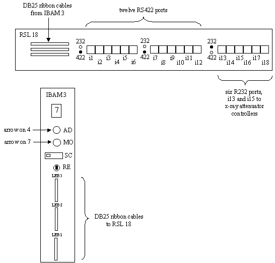
Connections between RSL 18 and IBAM 3 (DB25 ribbon cables) :
- top cable on RSL 18 : to LEB 3 on IBAM 3
- middle cable on RSL 18 : to LEB2 on IBAM 3
- bottom cable on RSL 18 : to LEB 1 on IBAM 3
Connections of RS232 ports on RSL 18 :
- on port i13 (for EH2 filters) : cable labeled : ID03 / S15 A (yellow plastic label) or NIM ID031 - XR ATT CTRL - RS232, VME ID031 - RSL 18 2 - i13(pink sticker)
- on port i15 (for EH1 filters) : cable labeled : ID03 / S25 A (yellow plastic label)
Below is the schematic drawing of the handshaking process between the x-ray attenuator controller and the VCT6 counter card :
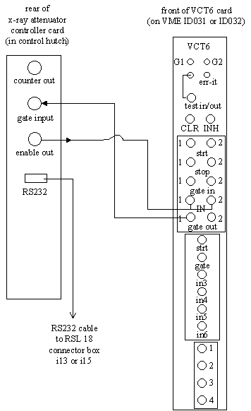
Connections to the VCT6 card (related to the filters system):
- VCT6 card of VME ID031 (for EH2) :
|
port
|
cable connected to this port
|
|
GATE IN 1, GATE IN 2
|
“T” toward BNC cable labeled :
NIM ID031 XR ATT CTRL GATE OUT VME ID031 VCT6 GATE IN 1 & 2 |
|
GATE OUT 1
|
BNC cable labeled :
NIM ID031 XR ATT CTRL GATE IN VME ID031 VCT6 GATE OUT |
- VCT6 card of VME ID032 (for EH1) :
The GATE OUT signal from the VCT6 is also used to control the small beam shutter in EH1 when using beam-sensitive samples (one closes the shutter all the time except during the counting).
|
port
|
cable connected to this port
|
|
GATE IN 1, GATE IN 2
|
“T” toward BNC cable labeled :
NIM ID032 XR ATT CTRL GATE OUT VME ID032 VCT6 GATE IN 1 & 2 |
|
GATE OUT 1
|
BNC cable labeled :
NIM ID032 XR ATT CTRL GATE IN VME ID032 VCT6 GATE OUT |
partners


European Synchrotron Radiation Facility - 71, avenue des Martyrs, CS 40220, 38043 Grenoble Cedex 9, France.