Accelerator and X-ray Source
Throughout 2011, the Accelerator and Source Division has continued its efforts to ensure reliable operation as well as upgrading a number of systems. Some new developments have been carried out and many of these are described hereafter.
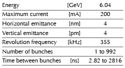
Beam parameters of the storage ring
Table 2 presents a summary of the characteristics of the storage ring electron beam.
 |
|
Table 2: Principal characteristics of the electron beam. |
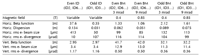
Table 3 gives the main optic functions, electron beam sizes and divergences at various source points. For insertion device source points, the beta functions, dispersion, sizes and divergences are calculated in the middle of the straight section. For bending magnets two representative source points have been selected for each type (even or odd cell number) of magnet, corresponding to magnetic fields of 0.4 T and 0.85 T. These points differ by the observation angles, of respectively 3 and 9 mrad from the entrance of the magnet.
 |
|
Table 3: Beta functions, dispersion, rms beam size and divergence at the various source points. |
Electron beam profiles are Gaussian and the size and divergence are presented in terms of rms values. The associated full width at half maximum sizes and divergences are 2.35 times higher. Horizontal electron beam sizes and divergences are given for the multibunch filling modes and apply to almost all filling patterns except when the current per bunch is larger than 4.5 mA, for which a slightly larger size and divergence are attained because of the increased energy spread of the electron beam.
Vertical electron beam sizes and divergences are given for a vertical emittance of 4 pm, which is now the standard for 2 x 1/3 and 7/8+1 filling modes. The vertical sizes and divergences are about 1.4 times larger in uniform filling mode (due to ion effects, which are partially corrected by the use of a vertical bunch-by-bunch feedback). To increase the lifetime of the stored beam, the vertical beam sizes and divergences are deliberately increased by about a factor 4 in the 16-bunch, 4-bunch and hybrid filling patterns.
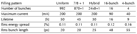
The lifetime, bunch length and energy spread mainly depend on the filling pattern. These are given in Table 4 for a few representative patterns. Note that in both 16-bunch and 4-bunch filling patterns, the energy spread and bunch length decay with the current (the value indicated in the table corresponds to the maximum current). The bunch lengths are given for the usual radio-frequency accelerating voltage of 9 MV (8 MV for 16-bunch and 4-bunch).
 |
|
Table 4: Current, lifetime, bunch length and energy spread for a selection of filling modes. |
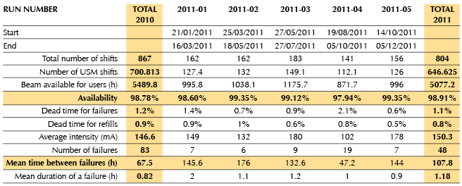
Summary of accelerator operation
In 2011, 647 shifts (5173 hours) of beam were initially scheduled. Out of these, 5077 were effectively delivered (including 39.2 hours of refill). This represents a beam availability of 98.91%, which is an excellent figure, barely lower than the all-time record of 99.04% for 2009 and slightly greater than the 98.78% for 2010. Dead time due to failures accounts for the remaining 1.1%. The number of failures has been reduced compared to 2010 thanks to the absence of noticeable repetitive failures. Undoubtedly the efforts in preventive maintenance (e.g. replacement of water flow-meters with more reliable ones) have been particularly beneficial this year. Consequently, the previous record for mean time between failure (76 hours in 2009) has been significantly bettered in 2011, reaching the excellent figure of 107.8 hours.
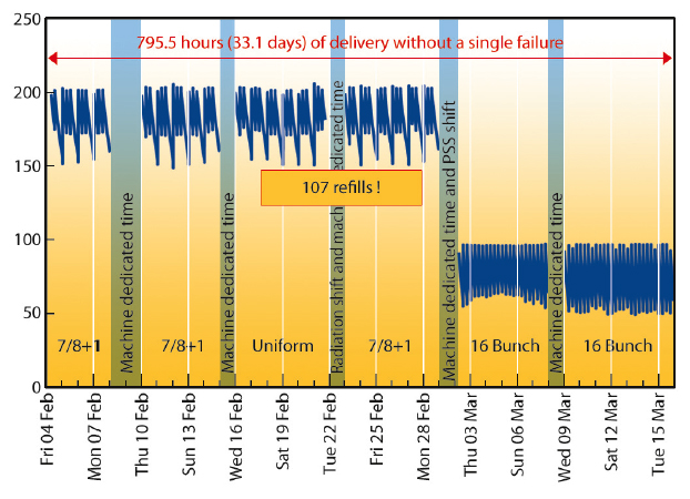
But that was not the only record for the year since, during the first run of 2011, the beam was delivered for 795 hours (33 days!) without a single failure and interrupted only by the scheduled machine dedicated days or radiation tests (See Figure 154). Besides this record, which was the first sign of a good year, others runs proceeded particularly well as there were 23 long delivery periods (each more than 100 hours) without a single interruption.
 |
|
Fig. 154: The ESRF record delivery without a single failure, interrupted only by scheduled machine dedicated days. |
Despite these excellent results, operation was particularly delicate due to the lack of redundancy on the radio frequency (RF) system caused by the installation of a new solid-state amplifier on the booster. Fortunately, this upgrade did not have a significant impact on the operation.
 |
|
Table 5: Overview of storage ring operation in 2011. |
Throughout the whole year, the beam was regularly delivered with a very low vertical emittance in multibunch modes. Table 5 presents an overview of operation in 2011.
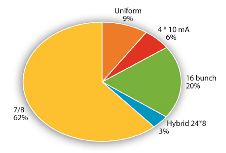
Filling patterns
Figure 155 presents the distribution of filling modes delivered in 2011. The only major change compared to 2010 is that the uniform mode is now limited to specific user requirements. The preferred standard mode is now the “7/8 +1” filling mode which has become the best compromise satisfying the majority of the different user communities.
 |
|
Fig. 155: Distribution of the longitudinal filling modes in 2011. |
With the exception of the specific timing modes (16 bunch, 4 bunch and hybrid) for which the lifetime has to be increased by deliberately increasing the vertical emittance, all others modes were delivered with the vertical emittance as low as possible, i.e. 5 pm.rad or lower.>
partners


European Synchrotron Radiation Facility - 71, avenue des Martyrs, CS 40220, 38043 Grenoble Cedex 9, France.