- Home
- High power radiofrequency solid state amplifiers
High power radiofrequency solid state amplifiers
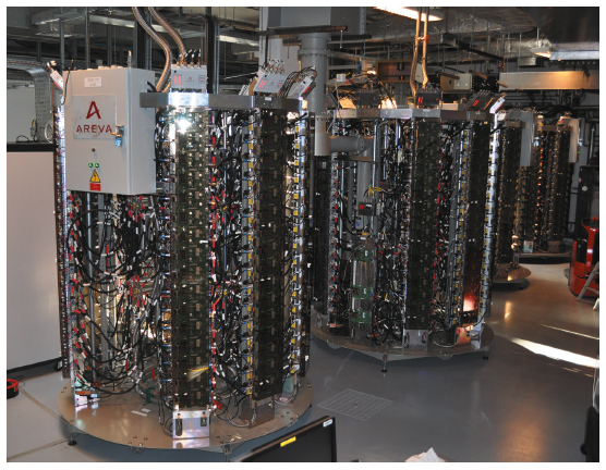
In autumn 2011, ELTA/AREVA delivered the first batch of four 352.2 MHz - 150 kW solid state amplifiers shown in Figure 162. These amplifiers were thoroughly tested with a dummy load and are now being connected to the booster cavities. They will be put into operation for the booster ring at the intermediate accelerator restart in March 2012. A second batch of three 150 kW amplifiers will be delivered later in 2012 to power the three new HOM-damped cavities on cell 23 of the storage ring [1].
 |
|
Fig. 162: First four 150 kW solid state amplifiers installed in the booster RF room. |
The main objectives for the implementation of these solid state amplifiers in phase 1 of the ESRF upgrade are:
• Qualifying solid state amplifiers as alternative to high power klystrons to guarantee the long term operation of the ESRF, thereby preparing a possible replacement of other klystron transmitters in further upgrade phases.
• Saving electrical power on the booster: thanks to the anti flicker system needed for the cycling at 10 Hz (huge capacitor banks with a total of 3.2 F in the 280 V DC power supply) up to only 400 kW will be drawn from the mains as compared to 1200 kW with the former klystron transmitter.
• Qualifying with beam a new storage ring RF unit comprising three HOM-damped cavities powered by three solid state amplifiers, which replaces one five-cell copper cavity powered by a klystron.
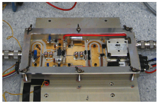
ELTA has benefited from a transfer of technology from SOLEIL, where the elementary building blocks were qualified. For this project, SOLEIL developed a new RF module using the latest sixth generation LDMOS-FET (BLF578 from NXP), which allowed a doubling of the nominal power of the basic RF module from 330 W in the existing SOLEIL amplifiers to 650 W for the ESRF amplifiers (Figure 163). By combining the power from 128 such RF modules, a single coaxial combiner tree or “tower” delivers more than 75 kW. Only two such towers are needed to build a 150 kW amplifier.
 |
|
Fig. 163: 650 W RF module under test. |
The RF modules are mounted on water cooled plates together with individual 280 VDC to 50 VDC converter boards. The 280 V DC power supplies and the anti-flicker system for the booster were implemented in collaboration between the RF Group and the Power Supply Group.
References
[1] J. Jacob, J.-M. Mercier, M. Langlois and G. Gautier, 352.2 MHz - 150 kW Solid State Amplifiers at the ESRF, IPAC’2011, San Sebastian, Conference proceedings pp. 71-73 (2011).
partners


European Synchrotron Radiation Facility - 71, avenue des Martyrs, CS 40220, 38043 Grenoble Cedex 9, France.