- Home
- News
- Spotlight on Science
- X-ray colour provides...
X-ray colour provides direct 3D information in crystallographic texture measurements
25-08-2016
Preferred crystal orientation (crystallographic texture) is a common phenomenon in many complex micro- and nanocrystalline materials of biological and synthetic origin. Conventionally, texture determination by XRD involves sample 2D diffraction images combined into 3D information by sample rotation. We have shown that the photon energies (“X-ray colours”) in a white X-ray beam can be exploited to gain direct 3D crystallographic information in texture measurements. The functionality of the method was demonstrated on carbon fibres and lobster cuticle.
Share
For many decades, crystallographic texture has been measured by X-ray diffraction involving a monochromatic beam and state of the art area detectors. Conventional area detectors, however, are only capable of delivering intensity information in every pixel and hence yield a 2-dimensional “grey-scale” diffraction image. True 3D information about crystallite orientation could only be obtained by rotating the sample in the beam and by collecting diffraction images at different rotation angles. This puts severe limitations on the exploration of complex materials, since the local crystallographic texture may change dramatically from one point to the next, even on the micrometre scale. Prominent examples are found in biology: bone, wood, teeth or sea shells all exhibit intricate crystallographic textures which are linked to the materials’ functionality and give important insight into their formation, growth and adaptation.
A new class of pixelated X-ray area detectors now allows the detection and discrimination of different photon energies in every pixel (pnCCD type detectors, SLcam) [1]. Together with a polychromatic X-ray beam, such detectors can be used to achieve “X-ray color images”, which have already proven useful e.g. for full-field fluorescence imaging of the chemical composition of materials [2]. Moreover, the “X-ray colours” also provide enhanced information in diffraction experiments. Due to the sensitivity of the diffraction condition to both, crystallite orientation and incident energy, X-ray photons of different energies probe different crystal planes in the sample. This can be exploited to collect information from different crystal plane orientations, which is in fact routinely done in traditional Laue diffraction. However, in the conventional “grey scale” Laue pattern, the individual diffraction spots can be assigned for single crystals or for multiple only if very few crystal grains are in the beam. For truly polycrystalline samples, the pattern can no longer be interpreted due to the high number of overlapping spots. This obstacle can be overcome if the scattered photons of different energies can be discriminated (energy dispersive Laue diffraction, EDLD [3]).
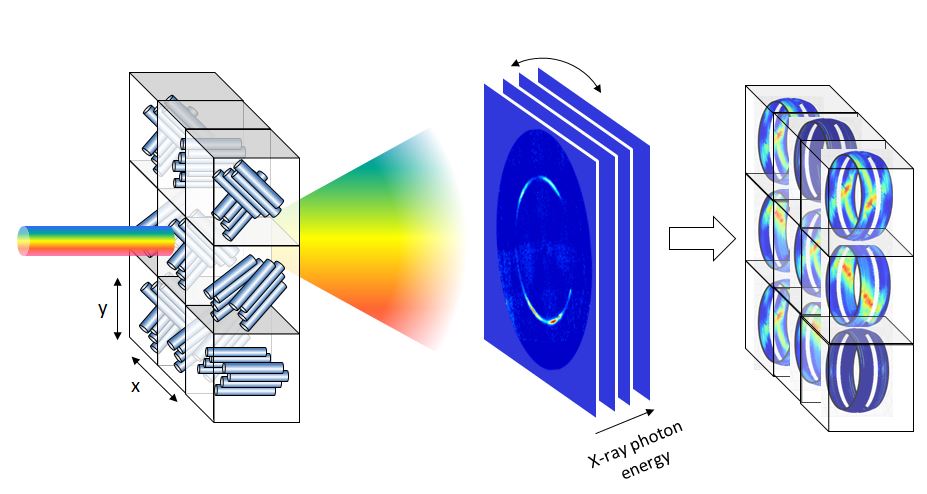
We have made use of this approach for crystallographic texture measurements for the first time and have performed an EDLD experiment at BM28. For this purpose we used the full white beam from the bending magnet together with an energy dispersive X-ray camera. The setup was specifically designed to exploit a wide range of scattering angles, i.e. a large angular portion of reciprocal space. The principle is shown in Figure 1.
 |
|
Figure 1. Crystallographic texture measurement by EDLD: a sample with locally different crystal orientations (here displayed as fibres) is raster scanned with a polychromatic beam. The energy dispersive X-ray camera delivers an energy spectrum for each pixel, which can be regrouped to obtain a stack of diffraction images at different energies. The local 3D scattering pattern can be displayed directly for each beam position on the sample. |
The sample was raster scanned and the conventional 2D diffraction information was complemented by an energy spectrum recorded in each pixel. By using a straightforward reconstruction algorithm based on the Ewald sphere geometry, the photon energies (“X-ray colours”) were used to calculate the missing third dimension in space. In this way a 3D representation of scattering data was achieved without a priori knowledge of the sample and without the need to rotate the sample.
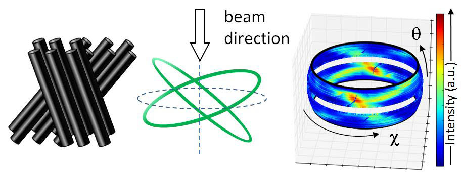
We applied the new texture measurement method to map the orientation of graphite planes in carbon fibres and of calcite crystallites in lobster cuticle. Since the technique yields 3D scattering patterns, complex textures such as the combination of different orientations can be displayed very well. The example of two crossed strands of carbon fibres is shown in Figure 2. The two orientations are immediately and directly visible from the 3D reconstruction of the scattering image. In lobster tail cuticle, the method revealed a calcite crystal orientation roughly perpendicular to the cuticle plane. At the same time, it also allowed determination of the Ca distribution, since the energy dispersive detector also records the X-ray fluorescence from the sample and thus yields chemical information as well.
 |
|
Figure 2. Example for EDLD texture measurements on two crossed bundles of carbon fibres (left). In reciprocal space, each carbon fibre yields a reflection ring from the (002) graphite planes perpendicular to the fibre axis (so called fibre texture). The crossed rings are observed directly in the 3D scattering patterns (right) and can be used to reconstruct the orientation of the carbon fibres. |
In this way, 3D crystallographic and chemical information could be acquired in a single shot, without sample rotation and at a lateral spatial resolution only limited by the beam size. The method is therefore of particular value for fast 2D texture mapping of complex samples or for any setup or system that does not allow rotation. The non-rotational setup and the 3D information makes the study of correlated effects conceivable, including crystallisation and strain development. The approach combines the benefits of both, traditional Laue diffraction and monochromatic diffraction, and can therefore be expected to become a powerful and elegant tool in future crystallography, applied chemistry and materials science.
Principal publication and authors
T.A. Grünewald (a), H. Rennhofer (a), P. Tack (b), J. Garrevoet (c), D. Wermeille (d,e), P. Thompson (d,e), W. Bras (f), L. Vincze (b), H.C. Lichtenegger (a). Photon energy becomes the 3rd dimension in crystallographic texture analysis, Angewandte Chemie Int. Ed. 55 (2016); doi: 10.1002/anie.201603784.
(a) Institute of Physics and Materials Science, Department of Materials Sciences and Process Engineering, University of Natural Resources and Life Sciences – BOKU, Vienna (Austria)
(b) Department of Analytical Chemistry, Ghent University (Belgium)
(c) Deutsches Electronen Synchrotron, Hamburg (Germany)
(d) XMaS -The UK CRG Beamline, ESRFGrenoble (France)
(e) Department of Physics, University of Liverpool (UK)
(f) Netherlands Organization for Scientific Research (NWO), DUBBLE@ESRF, Grenoble (France)
References
[1] O.Scharf et al., Analytical Chemistry 83, 2532-2538 (2011).
[2] P. Tack et al., Analytical Chemistry 86, 8791-8797 (2014).
[3] S. Send et al., J. Appl. Cryst 42, 1139-1146 (2009).
partners


European Synchrotron Radiation Facility - 71, avenue des Martyrs, CS 40220, 38043 Grenoble Cedex 9, France.