- Home
- Users & Science
- Scientific Documentation
- ESRF Highlights
- ESRF Highlights 2016
- Enabling technologies
- Liquid nitrogen cooled bent crystal Laue-Laue monochromator
Liquid nitrogen cooled bent crystal Laue-Laue monochromator
The ID31 Laue-Laue monochromator covers the energy range from 50 to 150 KeV. Its main feature is an adjustable energy-band which is proportional to the inverse of the bending radius of the Si(111) crystals. The key technical element is the cryocooled crystal bender based on a new design.
At high photon energies, silicon crystals become transparent to X-rays allowing monochromators to work in transmission geometry (Laue) instead of reflection geometry (Bragg). Furthermore, the extinction length increases in proportion to energy and any distortion of the crystal makes it diffract kinematically rather than dynamically [1]. This can be used to increase the flux when the highest resolution is not needed.
Bending of the crystal introduces an easily controllable distortion whilst the brightness of the source can be conserved. However, the thermal distortion due to the large thermal load introduces a thermal bump reducing the source properties. Therefore, the crystal should be cooled down to 125 K where the thermal expansion coefficient of silicon approaches zero and the heat conductivity increases.
Cooling and control of the geometrical shape of the bent crystal are complicated. Technical problems arise mostly from vibrations in the cooling circuit. Furthermore, at high X-ray energies, the angular widths of the reflections decrease, which further restricts the technical specifications. With all this in mind, the most desirable quality in the design of the Laue-Laue monochromator for ID31 was stiffness. In particular, the design of the bender has to allow stiff mounting of the silicon crystal even when the crystal is flat.
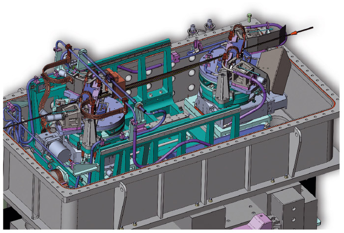
The ID31 Laue-Laue monochromator, located at 105.2 m from the source, covers the energy range from 50 to 150 KeV, characterised by an adjustable energy-band which is proportional to the inverse of the bending radius of the crystal. The Laue-Laue monochromator consists of two bent Si(111) crystals in non-dispersive geometry with an asymmetric cut of -36°. The crystals can be rotated so that other reflections in the (110) or (001) plane can be used, e.g. the Si(311) reflection with an asymmetric cut of -6.5°. The crystals are 5 mm thick. The beam offset can vary between 7 and 25 mm. To allow the full energy range with 20 mm offset, the second crystal has a translation along the incident beam from 250 to 750 mm relative to the other crystal. A 3D inside view of the monochromator tank is shown in Figure 154: each crystal tower has a sideways translation, coarse rotation, cross tilt and fine rotation stages; the tower of the second crystal (left in Figure 154) has, in addition, a 500 mm long translation stage along the incident beam. The beam stop before the second crystal is water cooled whereas both crystals are liquid nitrogen cooled. The support of each bender is thermalised with resistive heaters.
 |
|
Fig. 154: 3D inside view of the monochromator. |
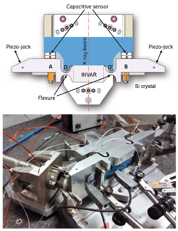
The key technical element is the cryocooled crystal bender [2] based on a new concept shown in Figure 155: the crystal is stiffly mounted at the points A and B on the cryocooled Invar bender. The bending is achieved with two piezo-jacks which are controlled in close-loop with the capacitive sensors, with a resolution of 20 nm. The positions of the flexures are chosen so that the crystal is cylindrically bent. The rigid part of the bender is strongly attached to the support. This concept of the bender allows stiff mounting of the silicon crystal even when the crystal is flat and therefore it is less sensitive to the vibrations caused by the liquid nitrogen cooling.
 |
|
Fig. 155: Top: Schematic diagram of the crystal bender. Bottom: The prototype of the bender. |
Copper cooling parts are strongly attached on both sides of the bender and are in direct contact with the end parts of the crystal as well to ensure excellent thermal contact between the cooling parts, bender and the silicon crystal. Moreover, the absorbed power can be tuned with the up-stream attenuators so that the heat load on the first crystal is optimum. The crystals and bending mechanism are high vacuum compatible. An extensive study of thermal and mechanical distortion of the crystal benders was performed using finite-element analysis.
Both crystals are cooled down to liquid nitrogen temperatures, and their bending mechanism allows both concave and convex bending with a minimum absolute bending radius of about 20 m. This ensures a maximum flexibility in the positioning of the virtual source created by the upstream compound refractive lens system and a flexible choice of the energy band pass.
The Laue-Laue monochromator is now installed at ID31 and the first X-ray commissioning measurements are very promising. The stability in energy is better than 0.5 eV over long periods of time including refills. Note that the Darwin width, i.e. energy band pass of a flat crystal, at 70 keV is 10 eV. The maximum band pass of 500 eV at 70 keV was achieved when the crystals were bent down to 20 m bending radius. No broadening of the focus size due to the vibrations has been observed.
Authors
M. Mattenet, K. Amraoui, P. Got, A. Homs, B. Lantelme, G. Malandrino, B. Picut , L. Rousset, H.P Van Der Kleij, A. Vivo, H. Witsch and V. Honkimäki.
ESRF
References
[1] P. Suortti and C. Schulze, J. Synchrotron Rad. 2, 6-12 (1995).
[2] M.Magnin-Mattenet et al., MEDSI 2016 Proceedings (JACoW), accepted September 2016.
partners


European Synchrotron Radiation Facility - 71, avenue des Martyrs, CS 40220, 38043 Grenoble Cedex 9, France.