- Home
- Users & Science
- Find a beamline
- X-ray nanoprobe
- ID01 - Nano/Micro diffraction imaging
- Equipment on ID01
- Detectors - Experimental Hutch
- Point (0-Dimensional) Detectors
Point (0-Dimensional) Detectors
Index
- NaI scintillator counter (Cyberstar)
- Vacuum compatible NaI scintillator counter (Cyberstar)
- ROENTEC detector
- AMPTEK detector
- CdZnTe detector
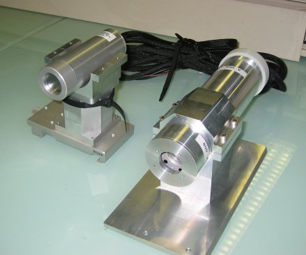
NaI scintillator counter (Cyberstar)
The "Cyberstar" detector is used in the vertical axis diffractometer (experimental hutch 1, EH1) mounted on the diffractometer detector arm.
It is a point detector normally used for energies from 5 keV to above 40 keV. It has a low noise (0.1 cps) and a relatively high maximum counting rate of ~ 2 x 10⁵ cps with 25% dead time.
For energies lower than 3 keV, the 200 microns Be window absorbs a substantial part of the incoming radiation (50% for 3 keV). Then, it can still be used, although care has to be taken when making comparison with absolute intensities taken at higher energies.
The scintillator used is a NaI(Tl) crystal providing a working energy range up to 50keV. The detector aperture is standard 32 mm diameter with a detector window in Beryllium of 0.2 mm thickness. After the scintillator there is a photo-multiplier tube with the photo-cathode adapted to the NaI(Tl) scintillation wavelength. The photo-multiplier has a typical gain of 10e6 providing an output pulse with rise time of 2.8 ns. Directly attached to the dynode chain there is a fast preamplifier.
In the back part of the detector housing there are a Lemo ERA size zero connector for the high voltage and an Anphenol 17DMW connector for the preamplifier power and signal output.
The control electronics Cybestar Model CS93PPU is located in a rack NIM in the rack 08 of the control hutch. This electronics integrates the high voltage power supply, the shaping amplifier and the single channel analyser. In the rear panel there is a DB9 female connector for the preamplifier power, a bnc for the signal input and a high voltage bnc for the photo-multiplier high voltage output. The unit is equipped with a serial line communication port configurable between RS232 or RS485. The DB9 male serial line connector is located in the rear panel.
The photo-multiplier voltage is adjustable between 250V and 1250V by means of a 10 turns potentiometer in the front panel. A 3 1/2 digit led display provides the reading of this voltage.
The amplifier gain can be continuously adjusted between 0 and 10 by a ten turn potentiometer located in the front panel. The shaping constant can be changed by a 4 position rotary switch.
The low level discriminator threshold and the upper level threshold are adjustable between 50 mV and 10V by two ten turns potentiometer in the front panel. A four positions rotary switch is used to change the operation mode of the window discriminator:
  -n normal:     Upper and lower level are separately adjustable
                 between 0 and 10V.
  -i Integral:   Upper level disabled.
  -a asymmetric: Upper level adjust between 0V and 1V the window above the
                 lower level.
  -s symmetric:  Upper level adjust symmetrically between 0.5V and -0.5V above
                 and below the lower level.
The amplified signal is present at the signal out bnc connector in the front panel. The discriminator output is a TTL or negative current fast Nim logic level jumped selected in the printed circuit board. The out put signal is accessible at the window out bnc output in the front panel.
The control unit can be remote controlled through the communication port. To use this feature the local-remote switch in the front panel must be set to remote (red light on). From this moment the control unit can be controlled only by the control program (spec, etc...).
The recommended operation settings are:
- High Voltage: 1000 V
- Gain : 5
- Peaking time: 0.5 - 1 usec.
- TTL Fast NIM: TTL
-
if an analyzer system is mounted
- Discriminator mode: Integral (i)
- Lower level: 0.5 - 1 V
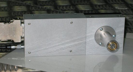
Vacuum compatible NaI scintillator counter (Cyberstar)
Its characteristics are very similar to the regular cyberstar detector (see above).
A model specially developed for ID1 for vacuum compatibility allows working at atmospheric pressure and in vacuum (e.g. 1 x 10⁻³ Torr) as well as in the difficult intermediate pressure range (the sealed detector head includes the photo multiplier high voltage source, to avoid problems associated with flashover at cabling connections).
The recommended operation settings are:
- High Voltage: 800 V
- Gain : 5 ???
- Peaking time: 0.5 - 1 usec. ???
- TTL Fast NIM: TTL ???
ROENTEC detector
This is the commercially available X-flash silicon drift diode normally used for energies from 3 keV to 15 keV. Its main advantage is that it is very fast; its maximum throughput count rate is about 300 kcps at 60% dead time loss. It has a resolution of about 180 - 200 eV at 6 keV and an aperture of 2.5 mm diameter.
AMPTEK detector
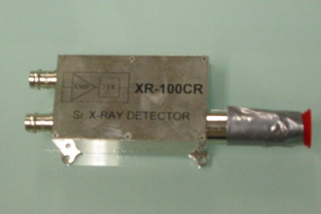
It is based on a Si diode (300 microns thick) with Peltier cooling. As the Roentec and the CdZnTe detector, it is a photon counter. Its energy range is from below 3 to ~ 20 keV. Its maximum count rate is quite low, about 10 kcps, but is has the advantage of being commercially available in a vacuum compatible package. Its resolution is about 180 eV and it is somehow fragile against radiation damage.
CdZnTe detector
This is a photon counter especially suitable for high energies. It can be used from 3keV to > 100 keV (figure 7). The energy resolution is about 800 eV when the detector is cooled to –20C. The maximum count rate is about 10 kcps.
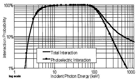
Fig. 4. Efficiency vs. energy for the CdZnTe detector. One can see the very large operation range of this detector (3-100 keV) with a very high efficiency.
partners


European Synchrotron Radiation Facility - 71, avenue des Martyrs, CS 40220, 38043 Grenoble Cedex 9, France.