Pinhole (U)SAXS/WAXS camera
Pinhole SAXS/WAXS and USAXS in one instrument
The SAXS/WAXS setup consists of three slits, two collimation slits, one before the monochromator at 29 m (P2) and the other after the mirror at 50 m (S3). Two guard slits (S4) are located at 61 m and directly before the sample at 65 m (S5). Usually the slit apertures are set to twice the full width at half maximum (2 x FWHM) of the focused monochromatic beam. The slits confine the region around the primary beam in which diffuse parasitic scattering from the optics is visible. This defines the minimum size of the beamstop and the minimum observalable scattering angle. A beam collimation system is foreseen to further curtail the parasitic background.
The three (U)SAXS detectors are mounted on a wagon inside the 34 m detector tube. The sample-to-detector distance can be varied from 0.8 m to 31 m covering a wide scattering wave vector q-range, 10-3 nm-1 < q < 8 nm-1, where q=(4π/λ) sin(θ/2), with λ the wave length (~0.1 nm) and θ the scattering angle. The q resolution limited by the beam divergence (~5 μrad) and size (~30 μm) is about 4x10⁻⁴ nm-1.
The 2-d WAXS option permits time-resolved combined SAXS/WAXS studies of oriented systems. Typically, the WAXS detector covers the q-range; 5 nm -1 < q < 50 nm -1 and the angular resolution determined by the point spread function of the detector is about 0.01°. With the WAXS option, the shortest SAXS detector distance is about 0.8 m, which permits an overlap between SAXS and WAXS q-ranges. Both detectors are hardware synchronized by a time frame generator that also triggers the fast beam shutter (FBS), and the multi channel scaler used to acquire the beam monitor (PIN diodes) counts and other optional signals.
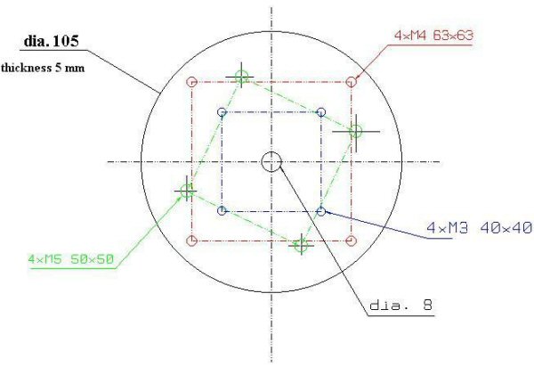
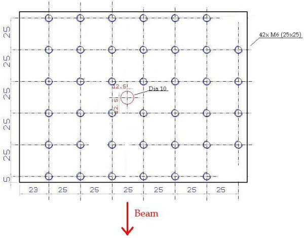
At the sample position a motorized horizontal translation table (with about 400 mm of motorized travel range and 800 mm total range) and a vertical translation stage (100 mm of range) with a motorized rotation around the vertical axis is available. If no rotation stage is required, the sample environment can be directly mounted on the fixed base plate (M6 holes, quadratic grid with 25 mm period - see figure below). The beam passes about 300 mm above the base plate. The available space is about (500 mm)3. For bulky experimental setups the vertical translation stage can be removed and the whole sample table with a usable area of 600 mm x 400 mm (M6 holes, quadratic grid with 25 mm period) can be used. The sample table has a maximum motorized vertical movement of 300 mm.
 |
 |
|
| plate of motorized rotation | base plate | |
|
click on the images to enlarge |
||
See beamline description for a complete list of
- available sample environments
- available detectors
Further Information
- Back to the ID02 start page
- Back to the Beamline layout (overview)
- Overview of detectors for SAXS/WAXS and USAXS
- Sample environments
- Procedures for data acquisition and online reduction
- Scientific and industrial applications
- Recent publications at ID02
partners


European Synchrotron Radiation Facility - 71, avenue des Martyrs, CS 40220, 38043 Grenoble Cedex 9, France.