- Home
- Design considerations for the ESRF Upgrade Programme EX2 slab
Design considerations for the ESRF Upgrade Programme EX2 slab
Expected probe sizes on the ESRF upgrade beamlines will range between 20 and 50 nm. With a probe size of 50 nm and an acceptable 10% drift, translational and rotational stability tolerances are 15 µm and 100 nrad. These tolerances must be respected for the duration of a scan which taken to be a maximum of 30 minutes.
Although vibrational stability of the new EX2 experimental hall slab is a key element in its design, measurements and simulations indicate that movements driven by temperature variations may be the dominant stability constraint. The ESRF has made high precision levelling and hydrostatic levelling system (HLS) measurements to characterise these and other site movements.
Several systematic ground movement signatures have been identified at the ESRF. These long-term movements do not directly influence experiments, but they do have to be considered in the design of a beamline. Beamlines can be subjected to millimetres of vertical uplift or subsidence with respect to the X-ray beam over their lifetime. So sufficient alignment stroke should be designed into instrument supports.
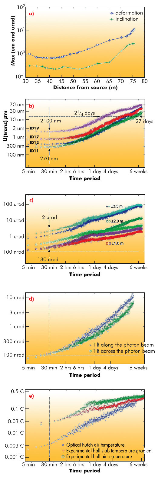
Recent tests using HLS on BM18 show large deformations at the support columns due to the passage of the overhead crane. This is not surprising; however, deformation reaches right across the slab. Indeed movement between 3 and 5 µm is even measured on the X-ray beam. This indicates that the ground deforms and the slab – regardless of thickness – follows the deformation. Although these deformations are only a nuisance, maximum measured inclinations along the beamline 0 mrad axis vary between 200 and 500 nrad. These movements are substantially outside of desired EX2 tolerances (Figure 150a).
Figure 150b shows variability in vertical movements on four ESRF long beamlines ID11, ID13, ID17 and ID19. Although movements are within desired EX2 tolerances, normalising the data to beamline length and extrapolating to a 250 m long beamline gives uncertainty estimates that reach 15 µm in less than 3 days. This demonstrates the necessity for frequent re-alignment and reflection in appropriate design.
 |
|
Fig. 150: a) Maximum deformation and inclination along the 0 mrad line from the source point due to the passage of the overhead crane charged with a 5.7 T load. b) Vertical movement uncertainty growth on ID11, ID13, ID17 and ID19. c) Slab curling as a function of time and position. d) Slab tilt uncertainty growth along and across the X-ray beam in an air conditioned optical hutch. e) Uncertainty growth in the optical hutch, experimental hall air temperature and temperature gradient through the existing slab. |
Rotational stability is far more challenging. Slabs curl non-linearly as a function of temperature (and/or humidity) gradient through them. Considering the temperature under the slab is essentially stable over several days, the main parameter driving the curling is the temperature variation in the experimental hall and hutches. Curling at the edge of the existing slab is 50 µm/°C. Figure 150c shows rotational uncertainty growth on the ESRF slab. Results are much better in an air-conditioned optical hutch (Figure 150d), but only just at the EX2 tolerance limit. The thermal uncertainty for the two cases is shown in Figure 150e.
The overhead crane results have led us to recommend restrictions on its use during USM. Indeed at the micrometre level, the slab and experiments are extremely sensitive to groups of people walking and forklifts circulating in the corridor. Although vertical movement tolerances are respected on the existing floor slab, measurements show that the 100 nrad rotational tolerance is largely exceeded in the experimental hall and is only just respected in an air-conditioned optical hutch. Because the curling effect is theoretically exacerbated in thicker slabs, one of the real design challenges for EX2 is to optimise potentially conflicting parameters such as mechanical rigidity with thermal performance. The measurements discussed here have helped to advance this challenge.
Author
D. Martin.
ESRF
References
[1] D. Martin, Some Design Considerations for the ESRF Upgrade Program Experimental Hall Slab, 11th International Workshop on Accelerator Alignment, 2010, DESY, Hamburg (Germany).
partners


European Synchrotron Radiation Facility - 71, avenue des Martyrs, CS 40220, 38043 Grenoble Cedex 9, France.