- Home
- Users & Science
- Find a beamline
- ID31 - High-energy beamline for buried interface structure and materials processing
ID31 - High-energy beamline for buried interface structure and materials processing
Synopsis
ID31 is dedicated for interface and materials processing studies using high energy X-rays. It offers a portfolio of hard X-ray characterisation techniques including reflectivity, wide and small angle diffraction (SAXS and WAXS, both in transmission and grazing incidence geometry), imaging methods, auxiliary techniques, coupled with a great versatility in choosing beam sizes, energy and energy-band.
Status:
open
Disciplines
- Environmental Sciences
- Chemistry
- Materials and Engineering
- Physics
- Life Sciences
Applications
- Energy conversion and storage
- Devices
- Electrocatalysis
- Additive manufacturing
- Metallurgy
Techniques
- Compton scattering
- GID - grazing incidence diffraction
- GISAXS - grazing incidence small-angle scattering
- SAXS - small-angle X-ray scattering
- WAXS - wide-angle X-ray scattering
- XRD - X-ray diffraction
- XRR - X-ray reflectivity
- Pair-distribution function analysis
- SXRD - surface X-ray diffraction
- XRF - X-ray fluorescence
Energy range
- 21.0 - 150.0 keV
Beam size
- Minimum (H x V) : 1.0 x 0.5 µm²
- Maximum (H x V) : 2.0 x 1.0 mm²
Sample environments
- Electrochemical cells
- Electrolyzer cells
- Hydrogen Fuel cell
- Fuel cell testing station
- Capillary cells
- Gas loading system up to 100 bar
- High temperature (2000K)
Detectors
- DECTRIS PILATUS®4 X 4M
- MAXIPIX
- 13-element solid-state Ge detector
- SMARTPIX
- Perkin Elmer XRD 1621
Technical details
Technical description
ID31 beamline overall layout
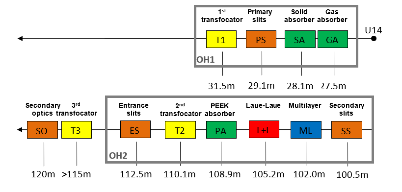
Figure 1. General optics layout in ID31. The upper panel shows the components in the first optics hutch (OH1), whilst the lower panel shows the components in the second optics hutch (OH2) and the experimental hutch (EH, with third beam transfocator and secondary optics) The secondary slits can be used as a pinhole monochromator.
X-ray source
The source of photons at the ID31 beamline is an in-vacum cryo-cooled undulator with 14.5mm period (U14). It provides the highest possible intensity in the energy range 20-150keV. Figure 2 compares the U14 with the U22 used previously at high energy diffraction beamlines.
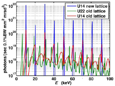
Figure 2. The X-ray source of the ID31 beamline is an in-vacuum cryo-cooled undulator with a period of 14.5 mm. This figure shows the brightness of the U14 undulator installed in ID31.
Experimental Hutch -EH
The experimental hutch (EH) is a white beam hutch which holds several equipment: the high precision imaging and diffraction instrument (MicroStation), an auxiliary detector table, the High Energy Micro Diffraction instrument (HEMD) with its detector table, and the WAXS and SAXS detector assemblies at very end of the hutch. The large granite structure supporting the area detector enables a flexible use of the detector with the sample stations including users setups, which can be installed on the hutch floor. A schematics of the ID31 experimental hutch is shown in Figure 3.
The experimental stations can be easily converted for different experimental approaches.
The SAXS flight tube can also be installed on supports between the sample stations and the SAXS detector located at the end of the hutch.
Large area WAXS detector can be moved along 12m longitudinal granite beams supported by granite pillars, as well as sideways and vertical, allowing detector positioning with respect to the incident beam and moving detector out from the beam when the downstream SAXS detector is used.
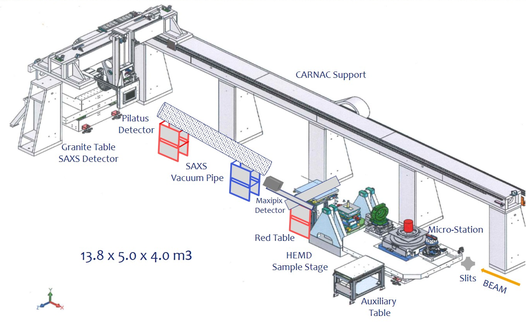
Figure 3. Experimental Hutch (EH) of the ID31 beamline.
- MicroStation instrument
This station is a high-resolution diffraction and imaging system based on a modular design. It consists of a heavy-duty sample positioning and scanning system (hexapod) with the possibility having optional modules before or after the sample.
The main components of the sample positioning and scanning system are translation, tilt and rotation stages and the sample positioning hexapod. The first three components are high precision scanning axis for reflectivity, reciprocal space mapping and tomography scans, and a Symétrie hexapod - Model Zonda - is used for sample positioning. The sample environment, often provided by the users, is mounted on the top plate of the instrument (red cylinder in Figure 6). The actual spatial resolution of the sample stage is about 100 nm. Figures 4 and 5 are schematics drawings of the MicroStation in the ID31 beamline.
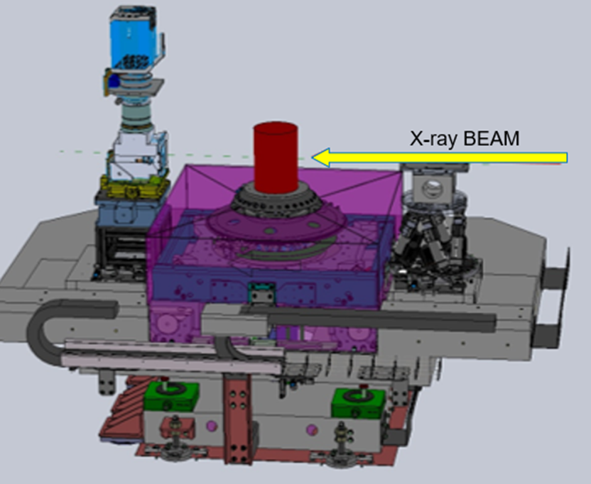
Figure 4. Scheme of the MicroStation instrument installed in the experimental hutch of the ID31 beamline.
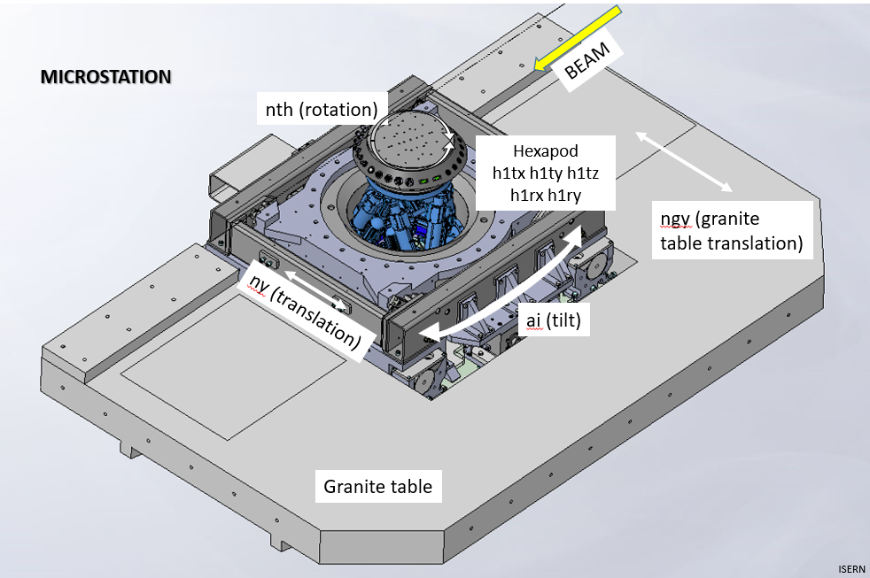
Figure 5. Scheme of the MicroStation instrument indicating the different motions.
The optional modules before or after the sample are mounted on small granite blocks which can be easily moved on air cushions. There are modules for:
1) Compound Refractive Lenses (CRL) system on a hexapod (Symétrie, Zonda Model)
2) High resolution diffraction and imaging instrument
3) Secondary optics system used to vertically deflect the incident X-ray beam to aliquid sample surface
4) High throughput powder diffraction robot
5) WAXS/SAXS-CT sample tower for large samples and for the primary beam flight-tube when the heavy-duty instrument station (HEMD, see next paragraph) is used
These modules can be used with both, the heavy-duty instrument or with the SAXS table located at the end of EH.
- Heavy duty instrument: High Energy Micro Diffraction - HEMD
The existing HEMD instrument (see Figure 6) was moved to ID31 from ID15A. It is designed for reflectivity and diffraction measurements using few micron beams and allows using heavy sample environment equipment (up to 300kg).
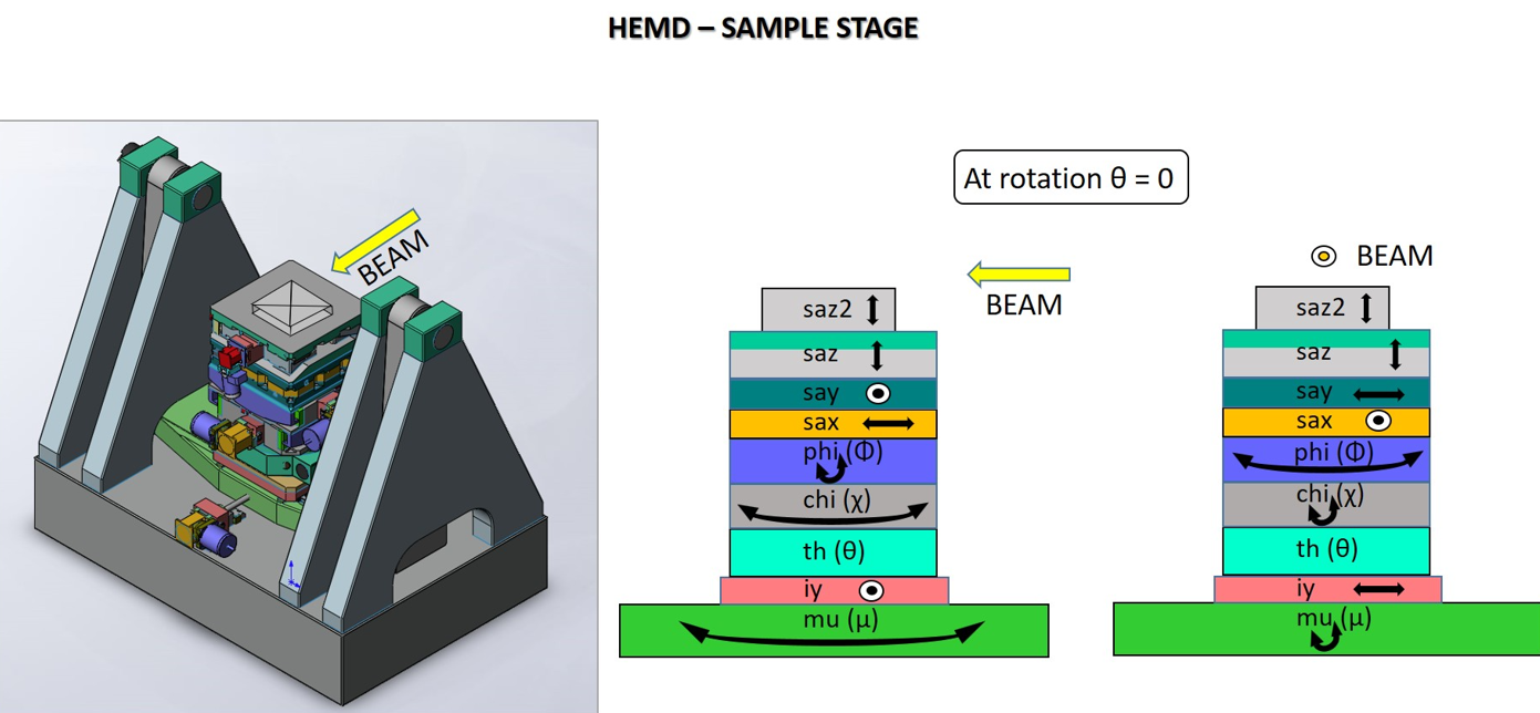
Figure 6. Heavy duty micro diffraction instrument - HEMD - installed in the experimental hutch of the ID31 beamline.
- High resolution diffraction and imaging instrument
The high resolution diffraction and imaging instrument is designed for experiments using very small beam (down to 200nm). It houses the third transfocator, a nano positioning sample tower and an imaging detector setup, all on their own granite blocks.
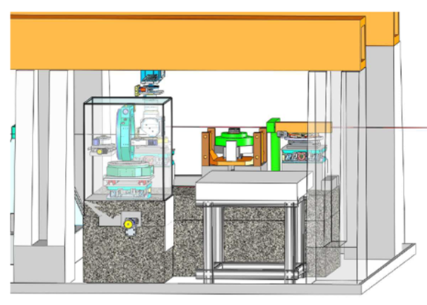
Figure 7. Scheme of the high resolution diffraction and imaging instrument installed when needed in the experimental hutch of the ID31 beamline.
Optics Hutch 1 - OH1
The white beam optics hutch (OH1) holds the following elements: gas and solid absorbers, high power slits, beam transfocator (T1), white beam viewer and beam mask.
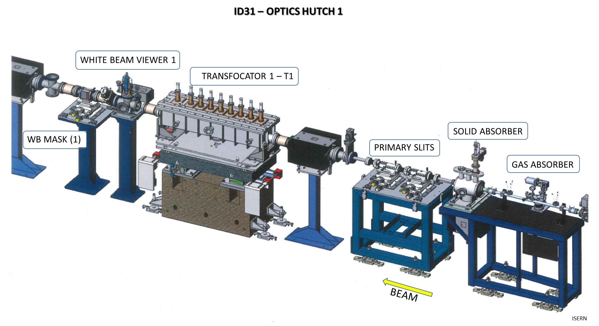
Figure 8. Elements of the Optics Hutch 1 (OH1) installed in the ID31 beamline.
Optics Hutch 2 - OH2
The optics hutch 2 (OH2) holds the following elements: high power slits, multilayer monochromator (for energies < 80 keV, 0.3% bandwidth), Laue-Laue monochromator (for energies > 50 keV, tunable bandwidth), white beam viewer, beam mask, monochromatic beam viewer, beam position monitors, beam transfocator (T2), solid absorber, high power double slits, and beam shutter. All monochromatic beam equipment are on motorized long granite tables to guarantee their simultaneous offset movement.
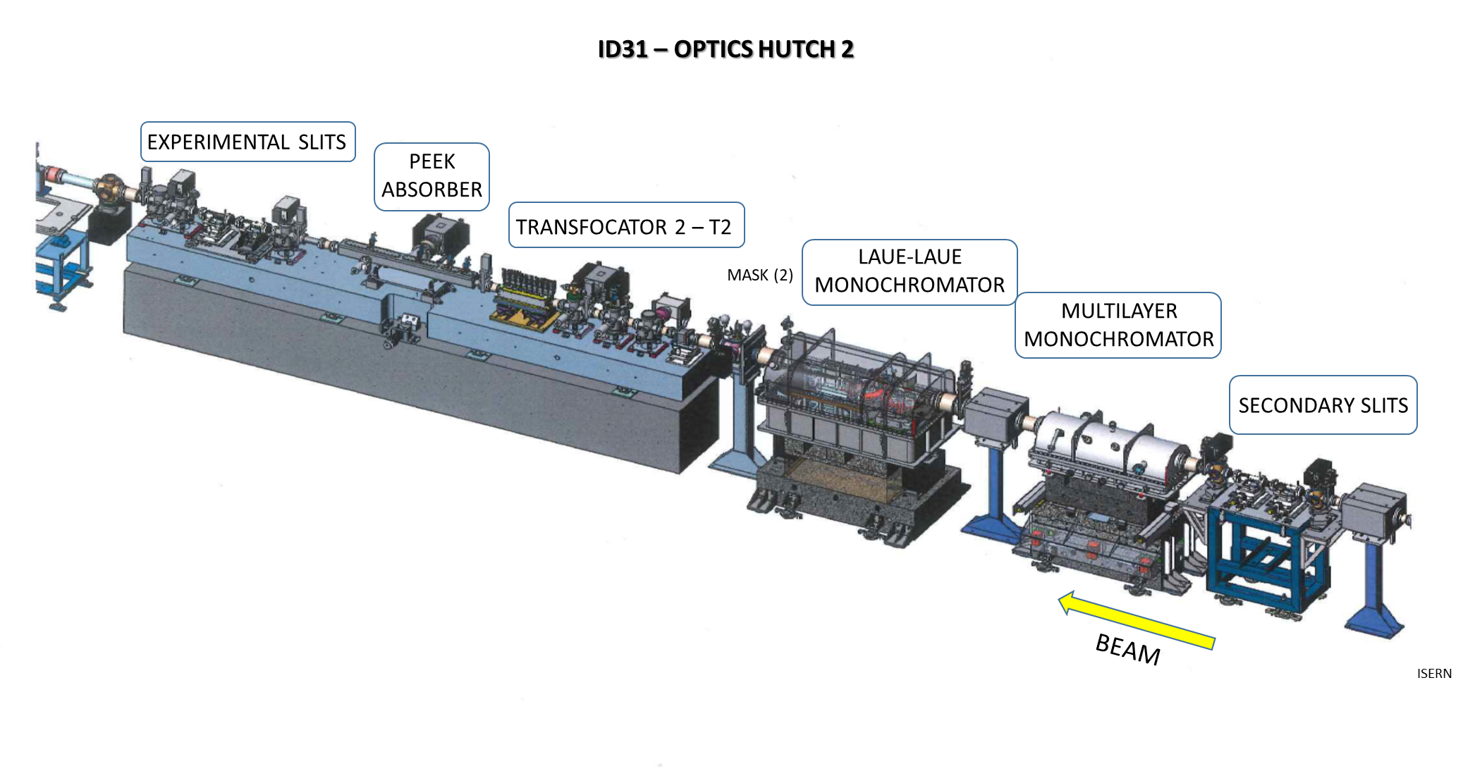
Figure 9. Elements of the Optics Hutch 2 (OH2) installed in the ID31 beamline.
- Focusing
The focusing optics consists of three transfocators:
1. A white beam transfocator in optics hutch 1 (T1, to condense the incident beam when very intense beams with medium range spot sizes are needed)
2. A monochromatic beam transfocator in optics hutch 2 (T2, to focus a beam up to 3.0 x 20.0 µm² with low divergence)
3. A monochromatic beam transfocator in the experimental hutch to provide sub-micron beams
Typically the first transfocator is used to prepare a parallel beam at the desired beam energy, and after the monochromator the beam is focused on the sample. In this way one can enhance the beam intensity by a factor of ten, whilst the focus size is broadened only about 50%.
- Monochromators
The two monochromators are installed inside OH2 just before the second transfocator (T2). Above an energy of 50 keV, a bent Laue-Laue monochromator in fixed-exit geometry and in horizontal scattering plane is used. Below 50 keV the absorption of this monochromator becomes significant and a multilayer monochromator in the horizontal scattering plane is used. For this 300 mm long flat water-cooled substrates with (NiV/B4C)500 coating are used. The multilayer monochromator is a basic ESRF standard design and its band width is 0.3%.
The Laue-Laue monochromator holds two bent Si(111) crystals with an asymmetric cut of -36o in non-dispersive geometry. The crystals can be rotated in a way that other reflections in the (1¯10) plane can be used. The crystal thicknesses are 5 mm and they are liquid nitrogen cooled. Since the virtual source can be either before or after the monochromator, the bending mechanism allows both concave and convex bending. The minimum absolute bending radius is about 20 m and the maximum is infinite, i.e., a flat crystal. The beam offset can vary between 7 and 25 mm. To allow the full energy range from 50 to 150 keV, the second crystal can be translated along the incident beam relative to the first crystal.
All the other elements after the monochromators inside OH2 are mounted on a 6 m long granite bench (see Figure 4) to follow the horizontal beam offset produced by the monochromator. The most important elements are the second transfocator (T2), the attenuators setup consisting in fused silica rods of various lengths which can be inserted in in the beam, and the slit system specifically designed for high X-ray energies.
partners


European Synchrotron Radiation Facility - 71, avenue des Martyrs, CS 40220, 38043 Grenoble Cedex 9, France.