- Home
- Users & Science
- Scientific Documentation
- ESRF Highlights
- ESRF Highlights 2017
- Enabling technologies
- Precision control and fiducialisation measurements for the EBS girder assembly
Precision control and fiducialisation measurements for the EBS girder assembly
The quality of the assembly, alignment and control of the key accelerator components are critical for the ultimate success of the ESRF’s Extremely Brilliant Source (EBS) project. Nearly 900 magnetic accelerator elements must be aligned to within 50-80 µm of their nominal positions for the new machine to function correctly.
Alignment starts with the fiducialisation of the magnets. It is important to correctly position the magnetic centre and orientation of the magnets, however, these are not visible or accessible quantities. Fiducialisation is the process of linking the magnet centre and axis to visible references installed on the exterior of the magnet. This process is carried out on a dedicated magnet measuring bench. The magnetic axis and centre of the magnet are materialised using a stretched wire, placed in such a way as to precisely emulate the position and orientation of the electron beam. The positions of the ends of the wire and the exterior reference points on the magnet are then simultaneously measured. Thus, the electron beam trajectory is known with respect to easily visible and measureable references on the exterior of the magnet.
The fiducialised magnets are then assembled on the girders in the dedicated assembly building, ESRF 01. The assembly of the girders is a complex activity comprising the installation and precise positioning of all of the accelerator elements: principally the magnets, but also the vacuum chambers and their sub-assemblies. Alignment and control are important at several critical points.
Before any assembly starts, the girder is aligned horizontally using jacks installed specifically for this purpose. Horizontality is not a precondition for the successful assembly of a girder but it is considerably easier to work in the gravity reference frame. Once the girder is in the horizontal position, a local girder frame of reference is created using the girder’s reference surfaces and survey sockets. This provides a physical and reproducible origin and orientation for the girder and all of its future sub-assemblies.
The magnets are then installed and finely aligned, a process that takes between six and eight hours to complete. This alignment consists of positioning the magnets in their nominal positions using their fiducialised references. All of the magnets, as well as the girders, have a nominal position in the EBS lattice. To establish their position on the girder, the 3D transformation of the theoretical magnet-centred coordinates of the reference points to their nominal girder-centred lattice positions is applied to the fiducialised magnet references. The positions of the magnets are then measured to ensure they are within the required positional tolerances.
Once this has been carried out, the magnets are opened and the previously assembled vacuum string is put in place. The permissible mechanical gap between the vacuum chambers and the magnet poles is very tight – less than 1 mm. To ensure these tolerances are respected, a certain percentage of the vacuum chambers are submitted to rigorous dimensional site acceptance tests (SAT) upon their arrival and all of the beam position monitor (BPM) positions are measured. This BPM fiducialisation provides 3D coordinates of the centre of the BPM buttons with respect to visible and measureable references on the exterior of the vacuum chambers. The fiducialised BPM references are then used to align the vacuum chambers on the girder and, once aligned, their positions are checked. After reassembly, the BPMs are quite difficult to access and measure.
 |
|
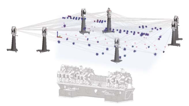
Fig. 152: To precisely determine the positions of all of the key elements on the girder, a highly redundant survey is made of all of the references installed on the magnets, vacuum chambers, BPMs, etc. Uncertainties of these measurements are less than 10 µm in X, Y and Z. |
The magnets are then reassembled and a final alignment check of everything: the magnets, vacuum chambers, absorbers and BPMs is carried out (Figure 152). The fully assembled girder is now ready for storage and installation in the tunnel. At this point, not only are the magnets and other elements – notably the BPMs – positioned to within a given tolerance, but their positions are also known to within a given uncertainty. This knowledge can be used very effectively to simulate the beam dynamics of the future machine.
 |
|
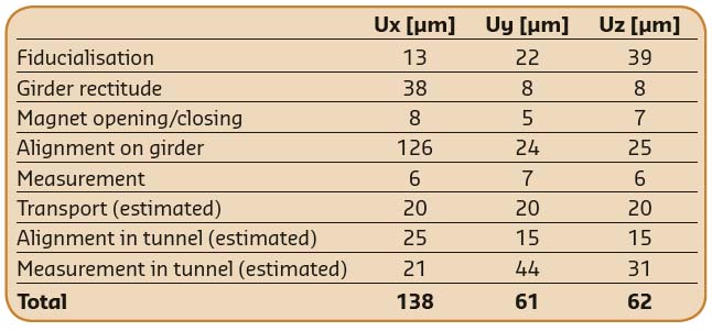
Table 2: Uncertainty estimate for the final magnet alignment in the storage ring tunnel. Uncertainty as presented here is discussed in the Guide to the Uncertainty of Measurement (GUM) published through the BIPM (https://www.bipm.org/utils/common/documents/jcgm/JCGM_100_2008_E.pdf). |
The overall quality of the alignment is given by an expression of uncertainty. This is the quadratic sum of the uncertainties of the alignment and measurements made at all the stages of the assembly process and during the final installation. The final estimated positional uncertainty for the EBS magnets in the tunnel is given in Table 2.
Authors
D. Martin. ESRF
partners


European Synchrotron Radiation Facility - 71, avenue des Martyrs, CS 40220, 38043 Grenoble Cedex 9, France.