- Home
- In situ fatigue analysis of dental implants with X-ray tomography
In situ fatigue analysis of dental implants with X-ray tomography
Prior studies revealed that conical titanium implants develop a microscopic gap at the implant-abutment connection (IAC). This microgap widens when the implant is subject to extra axial load. Since masticatory forces may cause mechanical fatigue of the implant, we use the IAC microgap as a marker for early cyclic deformation in fatigue experiments. To carry out the latter, an in situ setup was designed for synchrotron radiography and computed tomography, both of which can be recorded while the fatigue experiment is running.
Dental titanium implants play an important role in oral maxillofacial surgery. To prolong the lifetime of dental implants it is mandatory to investigate all aspects of possible failure. Recent studies reveal that a gap forms under load at the implant-abutment connection (IAC). This microgap is observed well below the yield of 600-1000 N and is thus believed to be the early onset of plastic deformation which first occurs at the IAC. In addition, the long-time reliability remains a very important issue mostly for clinical reasons. We have already studied the high cycle fatigue (HCF) for over 1 million load cycles by means of high-resolution synchrotron computed tomography (CT) [1]. Now we turn our attention to the cyclic deformation processes which need to be studied in situ in order to develop more durable implants. Similar to the HCF study, we propose to use the IAC microgap as a marker for early cyclic deformation, which is most likely to occur at the implant shoulder, hence at the IAC. Presuming that cyclic deformation might – by formation of a permanent microgap - cause the IAC to remain “open”, the IAC can be prone to bacterial colonisation and infection.
Synchrotron CT in combination with inline phase contrast was employed to examine the inner structure of the implant system. Through the analysis of interference fringes we detected small material interfaces which are enhanced. We showed that even for 2D radiography this technique can detect and measure microgap sizes down to 0.1 µm, which is well below the resolution of the X-ray images [2]. Thereby, in order to match the interference to simulations, prior knowledge of the sample such as the geometry and the refracting index of the material were used. Furthermore, propagation and tomographic projection can be considered two exchangeable linear operators; hence the technique of analysing the IAC microgap readily applies for 3D CT images as well. Moreover, since we investigate fatigue processes in situ, keeping the exposure time of the X-ray images short, i.e. of the order of milliseconds, is critical. The polychromatic “pink beam” (wiggler spectrum around 60 keV) at ID19 was best suited for this purpose.
2D and 3D images were recorded with a pixel sampling of 2.75 µm. A thick crystalline scintillator screen (250 µm GGG) allowed for a good signal to noise ratio even at exposure times of 10 ms (100 fps). In this mode we were able to record real-time radioscopy movies of the cyclic implant deformation (f = 2 Hz). For recording in situ 3D CT images during fatigue (f = 10 Hz), a single radiographic projection was recorded at the force peak of each load cycle while sample and fatigue machine rotate continuously. Hence, 1000 fatigue cycles were used for one scan assuming quasi stationary conditions during the loading. Altogether 10 scans (10 000 cycles) were recorded for one experiment, then the sample was replaced or the force was increased. This strategy represents a compromise between available beam time, the achievable number of fatigue cycles and the norm testing of dental implants.
The apparatus for in situ testing comprised a direct drive motor (LinMot, Switzerland) and a DC force sensor (Burster, Germany) for either constant-strain or constant-stress fatigue. For synchronising cyclic load, sample position and the trigger for image acquisition, the essential parts were controlled by a FPGA system (National Instruments, USA).
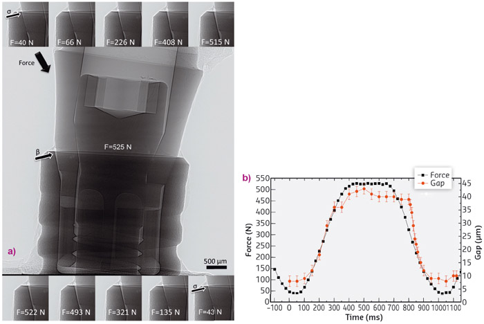
An example for real time radioscopy of a dental implant during fatigue is shown in Figure 37a. For each image the microgap was determined by the abovementioned method, the results of which are shown along with the measured forces in Figure 37b. The gap size was found to correlate well with the force, the latter changes from 40 N to 525 N peak (force ratio R ~ 0.1 was required), causing the microgap to open up to 43 µm. The sample was a BoneLevel Implant (Straumann AG, Switzerland).
 |
|
Fig. 37: (a) Representative frames from the real-time radioscopy experiment (middle maximum force). The gap opening at the implant shoulder is labelled with arrows, β indicates a big gap and s indicates a small gap. The loaded implant was a BoneLevel (Straumann AG, Switzerland). (b) Measured force vector and calculated microgap for each time point for one cyclic deformation cycle (approx. 1 Hz repeat). The error for the gap size is ± 2 µm and the error for the measured force is an estimation of ± 4 N. |
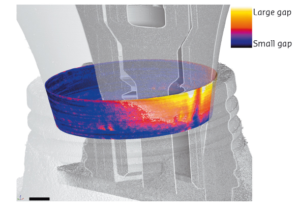
An example of 3D in situ CT of a NobelActive (Nobel Biocare, Switzerland) implant which was subject to mechanical fatigue during the scan is shown in Figure 38, peak force was 333 N. Figure 38 displays a composite view of the IAC gap (coloured conical surface) and the implant, which allows a qualitative appreciation of the gap size and location [3]. Through the observation of such cylinder projection maps of the microgap one can investigate the formation and the changes in the IAC-gap as a function of the number of cycles or as a function of peak-force.
 |
|
Fig. 38: Exemplary three-dimensional visualisation of an IAC microgap map (coloured) superimposed on the CT scan of the dental implant, indicating the orientation of the latter. Here the implant is a NobelActive (Nobel Biocare, Switzerland) under 333 N cyclic load. The look-up table is only a quantitative classification of the gap size. |
Real time radioscopy clearly is a powerful qualitative and quantitative tool for in situ observation of fatigue in dental implants or other similar metallic joints. The observed deformation was mainly elastic, when observed after short time offset and even at 525 N peak force. This preliminary result implies quasi-stationary conditions which are needed for recording tomographic images, as illustrated in Figure 38. By means of synchrotron in situ CT, complete 3D analysis of the IAC can be carried out. No changes were observed to occur from 1000 to 10,000 cycles. Yet, when load is increased, changes in gap size and lateral extension were detected. Surprisingly, the IAC became narrower during application of cyclic load.
In our study we have demonstrated a setup for real in situ investigation that does not require interruption of testing for CT scans to be recorded, but presumes quasi-stationary conditions over 1000 cycles and scans the sample during the cyclic loading. This mode is particularly important for fatigue studies which require a low or a negative force ratio. More generally, our setup is not limited to synchrotron X-ray sources, however, the photon flux has to be high to reach a sufficient signal to noise ratio at short exposure times.
Principal publication and authors
In situ microradioscopy and microtomography of fatigue-loaded dental two-piece implants, W. Wiest (a), S. Zabler (a), A. Rack (b), C. Fella (a), A. Balles (a), K. Nelson (c), R. Schmelzeisen (c) and R. Hanke (a,d), Journal of Synchrotron Radiation 22, 1492-1497 (2015); doi: 10.1107/S1600577515015763.
(a) Institute of Physics, University of Würzburg (Germany)
(b) ESRF
(c) Department of Oral and Maxillofacial Surgery, Medical Centre – University of Freiburg (Germany)
(d) Fraunhofer EZRT, Fürth (German)
References
[1] K. Blum et al., Dent. Mat. 31, 1415-1426 (2015).
[2] S. Zabler et al., Rev. Sci. Instr. 81, 103703 (2010).
[3] S. Zabler et al., Int. J. Mat. Res. 103, 207-216 (2012).
partners


European Synchrotron Radiation Facility - 71, avenue des Martyrs, CS 40220, 38043 Grenoble Cedex 9, France.