- Home
- Design and characterisation of the prototype girder for the ESRF-EBS storage ring
Design and characterisation of the prototype girder for the ESRF-EBS storage ring
One of the many challenges confronting the designers of the new storage ring is to significantly improve the vibration performance of the magnet assemblies whilst at the same time providing high-performance positioning systems which allow the alignment of one magnet to another with a precision of better than 50 µm.
In each of the 32 cells of the new storage ring there will be four identical girders to support the magnets arranged along the electron beam trajectory. The magnet arrangement of girders one and two are symmetric about the centre of the cell to the third and fourth girders.
The girder has been designed to optimise rigidity in order to minimise the effects of vibration and also to maintain the long term alignment of the magnets with respect to one another in the machine, and with respect to the beamlines. Almost as important is the possibility to align the girders with a precision of ± 50 µm with a resolution of 5 µm in the directions perpendicular to the electron beam. The vertical motion is motorised to correct ground movements quickly and without significantly interrupting the machine operation. The alignment tolerance between adjacent magnets is 70 µm. This means that all errors combined in the alignment of a single magnet must not exceed 50 µm. Electron beam position monitors (BPMs), vacuum chambers and other components installed on the girders have similarly demanding alignment tolerances.
A prototype girder was delivered to the ESRF in April 2015. It has been used to test and improve the EBS girder design and the alignment and support systems installed on it. Although many of the girder parameters are now fixed, work continues and will only be finalised in 2016.
 |
|
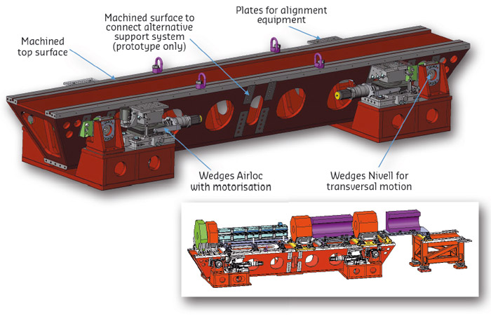
Fig. 154: The ESRF-EBS girder (empty) and loaded with magnets (inset). |
The girder is a steel box beam 5.1 m long (Figure 154). It weighs 3.1 tons empty and is supported by 4 commercially available Airloc wedges that have been motorised. Preloaded springs improve the stiffness of these components. They are used for vertical adjustment and the rotations about the longitudinal and radial girder axes. Because the system is statically indeterminate, very careful control of the wedges is required. Gliding surfaces under the wedges allow girder movements in the horizontal plane. Radial alignment movements including the rotation about the vertical axis are made using Nivell wedges preloaded with springs. Less demanding precision movements in the longitudinal direction are made through a simpler system of screws. The top surface and two longitudinal grooves are machined with a planarity of ± 50 µm over the length of the girder. They permit a precise pre-alignment of the magnets. The deformation of the girder under its full complement of the magnets is less than 40 µm.
A complete modal analysis of the equipped girder was made to ensure the first resonance frequency was above 50 Hz. This analysis included the floor and wedge stiffness. The wedge stiffness was determined in a dedicated laboratory experiment. The results of the test on the prototype confirmed the calculations without ambiguity.
High rigidity is required in order to limit the effects of vibration on the girder. Indeed, floor motion is the main excitation source and decreases proportionally to ~ 1/freq2. Therefore, the 1st vibration mode of the whole structure was designed to be in the 50 Hz region. The initial vibration measurements performed on the girder without dummy magnets revealed that this challenging target was accessible with a 1st mode at a remarkable 80 Hz. With the full set of dummy magnets installed the 1st vibration mode dropped to 42 Hz. This is a local mode of the so-called dipole-quadropole-2 magnet. The 2ndmode is also a local mode at 46 Hz for the sextupole magnet. A global girder mode occurs at 51 Hz. The displacement levels on the magnets are less than 1 µm peak to peak with weak amplification with respect to the floor.
Dummy magnets were installed on the girder to test fine alignment. A jig was successfully tested to facilitate the magnet installation to within 0.5 mm of their nominal positions. After installation, the magnets are fine-aligned. This has been tested several times. The uncertainty in the alignment of the magnets with respect their nominal positions (and one-another) was determined to be: 47 µm in the X direction along the electron beam direction; 25 µm in the Y direction perpendicular the electron beam in the horizontal plane; and, 37 µm in the Z direction perpendicular to the beam. The most critical alignment is in Y and Z directions.
An important number of tests have been performed on the prototype girder for a fine characterisation of all axis, X, Y and Z. These tests have simplified the original design on X and Y axis with a very good result. A fine Z characterisation showed us the possibility to move 10 tons within some few micrometres.
An extensive and redundant system of sensors (Hydrostatic Levelling System (HLS), Wire Positioning System (WPS) and inclinometers) are installed on the prototype girder. This installation serves two purposes: first it provides highly redundant information on how the girder moves and deforms; and, second it provides information that will be used to select the most appropriate system to equip the girders of the new machine.
Tests are ongoing to optimise girder performance. However the design of the girder is finished and production will commence soon.
Authors
T. Brochard, F. Cianciosi, L. Eybert, M. Lesourd and D. Martin.
ESRF
partners


European Synchrotron Radiation Facility - 71, avenue des Martyrs, CS 40220, 38043 Grenoble Cedex 9, France.