- Home
- X-ray wavefront metrology of pulsed beams using speckle tracking
X-ray wavefront metrology of pulsed beams using speckle tracking
A new way of measuring the beam wavefront has been created by observing the granular pattern from a piece of abrasive paper illuminated with a laser-like X-ray beam. A “transparent” detector permits images of the granular pattern to be captured simultaneously by two distinct detectors. A computer algorithm has been developed to interpret the beam wavefront from these images.
At-wavelength metrology is gaining in importance at large-scale X-ray facilities in order to take full advantage of the beams delivered by high-brilliance sources. Its applications are the optimisation of adaptive optics, monitoring and limiting thermal effects on X-ray optical elements, and the determination of the X-ray beam wavefront itself, the latter being a crucial input for the analysis of coherent scattering experiments.
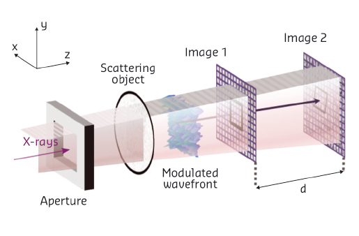
Using the experimental facilities at BM05 and ID22NI (now ID16A), we have successfully commissioned a new instrument based on the X-ray speckle tracking (XST) principle to enable the recovery of an X-ray wavefront from two images acquired simultaneously [1]. The schematic experimental setup is depicted in Figure 143. The incident X-ray beam passes through a thin phase object and, due to the partial coherence of the X-ray beam, the waves scattered from such an object interfere with the transmitted X-rays to generate speckles, i.e. random contrast features. When a 2D detector is then inserted along the beam trajectory within the so-called near-field region, the recorded image shows a granular pattern with high frequency features whose shapes vary little with the detector’s distance from the object. In this domain, the distortion of the interference pattern is only ruled by the wavefront transformation upon propagation in the Fresnel region. Therefore, when two images are recorded at different distances, it is possible by numerical processing to infer the trajectory of the X-rays from one image to the next and eventually deduce the exact shape of the wavefront.
 |
|
Fig. 143: Schema of the experimental setup for X-ray speckle tracking. |
The XST principle is based on computer cross-correlation algorithms capable of searching and identifying small subsets of pixels from one image to the other in an accurate and robust manner. In practice, a first assumption of rigid subset displacement allows the determination, with sub-pixel accuracy, of the vector field. The latter can then be used as an initial guess for a Newton-Gauss minimisation enabling the consideration of subset distortion (local curvature) that pushes the evaluation of the displacement vector to an accuracy close to 0.01 pixel. The simultaneous recording of two distant images avoids any contribution due to synchrotron beam instability and more importantly is ready to be used for pulse-to-pulse metrology at free electron lasers (FEL) where each bunch could present a slight wavefront difference from the others.
XST requires 2 detectors and the beam has to pass through either the first detector (as described here) or through both detectors (future development). For the first case, our approach was to use indirect illumination of CCD FreLoN cameras [2]. Most of the X-rays go through a thin garnet scintillator and a glassy carbon mirror (low absorption) orientated at 45° with respect to the incoming beam direction and continue their way to the second detector operating on the same principle. The image of the scintillator emitting visible light by luminescence is reflected at 90° by the mirror and transported by a microscope objective to the CCD chip. Numerical treatments are used to minimise the background noise and to correct the raw images for the inhomogeneous response of the scintillators and for the detector distortion.
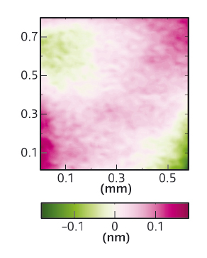
The online metrology setup was tested at the former ID22NI beamline to characterise a 29 keV energy beam focused down to a spot size of ~ 50 nm x 50 nm using multilayer-coated mirrors set in a Kirkpatrick-Baez arrangement. After data processing, two-dimensional images of the wavefront gradient were obtained with a spatial resolution as low as a few micrometres, impossible to reach with previous methods. The wavefront was then recovered by two-dimensional numerical integration of the phase gradient. The wavefront errors were derived by subtraction of the best fitting ellipsoid from the reconstructed wavefront. Figure 144 shows the results of such a reconstruction. The observed wavefront error is equivalent to a 45° astigmatism, which may be due to small sagittal focusing effects or orthogonal misalignment of the two mirrors of the upstream KB optical system.
 |
|
Fig. 144: X-ray beam wavefront errors determined experimentally with a distance of 510 mm between the two detectors. One can notice the scale amplitude in the order of the angstrom. |
In the present experiment, the horizontal and vertical wavefront gradient errors were in the order of 0.4 μrad and 0.7 μrad, respectively. The angular sensitivity could be improved to below 100 nrad by increasing, for instance, the propagation distance between detectors. This speckle-based instrument is expected to find future applications at FEL sources for the single-shot analysis of the X-ray pulses, provided further development of specific fast scintillators and semi-transparent mirrors with minimal degradation of the beam coherence and of the speckle pattern is undertaken [3].
Principal publication and authors
X-ray pulse wavefront metrology using speckle tracking, S. Berujon, E. Ziegler and P. Cloetens, Journal of Synchrotron Radiation 22, 886-94 (2015); doi: 10.1107/S1600577515005433.
ESRF
References
[1] See references included in the principal publication.
[2] J-Cl. Labiche et al., Review of Scientific Instruments 78, 091301 (2007).
[3] Project funded by the European Union’s Horizon 2020 research and innovation programme under grant agreement No 654220 (www.eucall.com).
partners


European Synchrotron Radiation Facility - 71, avenue des Martyrs, CS 40220, 38043 Grenoble Cedex 9, France.