High pressure
pressure cell for reactions in supercritical fluids
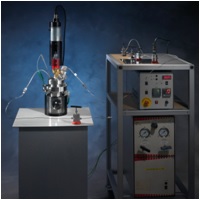
High pressure sample cell for in situ time-resolved X-ray scattering experiments designed for chemical reactions in supercritical fluids (pressures up to 210 bars and temperatures up to 120 °C) (Citation : Rev. Sci. Instrum.85, 093905 (2014); http://dx.doi.org/10.1063/1.4895717). Usage of this device has to be requested and discussed beforehand with beamline staff.
 |
The cell has a large volume in order to generate results relevant to industrial applications. The flexible design of the cell facilitates time resolved simultaneous SAXS-WAXS measurements in combination with additional techniques such as DSC, FT-IR or Raman spectroscopy. |
The cell consists of a 60 ml stainless steel autoclave fitted with a magnetically coupled overhead stirrer using a simple “paddle” blade (NWA GmbH) and motorised driver (RW20, Janke and Kunkel) turning at 300–400 rpm. The cell is composed of two parts: the top (head) section contains all the required services such as gas filling, stirring, and over pressure safety devices, whilst the main heating elements are in the bottom part (body) which contains the reaction volume (see engineering drawing below)
 |
Engineering drawing showing details of the high pressure X-ray scattering cell consisting of (1) head, (2) cell body, (3) clamp, (4) screwed window holder, (5) carbide window holder, (6) safety needle assembly, (7) Swagelok blow off valve, (8) paddle stirrer, (9) O-ring (EPDM 42 mm × 2 mm), (10) O-ring (BS019 EPDM 35 mm × 1.78 mm), and (11) overhead magnetic stirrer. Citation: Rev. Sci. Instrum.85, 093905 (2014); http://dx.doi.org/10.1063/1.4895717 |
The cell is manufactured from AISI 316/316L EN1.4401/4404 certified stainless steel bar. The cell body contains two threaded mounts with an inclusive angle of 40° for the diamond windows. The pressure, temperature, and stirring rate in the X-ray cell are operated remotely by a multi-component electronic control module. The pressure is monitored by a resistive bridge pressure transducer.The two components are joined via a clamping mechanism with a safety key to prevent the cell being opened while pressurised. The clamp sealed system facilitates the implementation on the services head of further auxiliary techniques such as Differential Scanning Calorimetry (DSC), FT-IR, or Raman spectroscopy equipment. The elastomeric seals can be changed so as to resist different solvent conditions; we use Ethylene Propylene Diene Monomer seals (EPDM, −55 to 150 °C) with supercritical CO2.
The control module is fitted with a trip system (West 6700+) that is triggered if the pressure exceeds 240 bar or if the maximum working temperature is exceeded by an internal thermocouple reading; this trip switches off the heating jacket. The operational integrity of the cell is protected by two devices: (I) a preset spring loaded proportional relief valve, set to 240 bars to protect the working integrity of the cell (labelled (7) in the above engineering drawing); (II) a 310 bar rupture disc to protect the structural integrity of the cell.
Temperature is controlled to ±1 °C via a Eurotherm 3216 PID controller. The control thermocouple is located in the external heating jacket. The internal temperature of the cell is monitored by a second thermocouple placed inside the head. The multi-component electronic control module can be operated by a LabView program that logs the working pressure and temperature.
The reaction conditions are monitored via an internal 316 stainless steel sheathed K-type thermocouple (Ø = 1.5 mm) and external pressure transducers (RDP Electronics type A-105 transducer, 690 bar maximum). HIP high pressure valves and Swagelok tubing and fittings were adopted to connect the system to the pump.
The internal path length can be changed by interchanging the threaded window mounts for different experiments. This permits optimisation of the X-ray path length as function of scattering density contrast and wavelength versus absorption. The clear optical aperture for the autoclave is 40° which allows simultaneous SAXS/WAXS measurements.
We use windows made from synthetic single crystal diamond type III supplied by Element 6. X-ray equipment traditionally uses natural diamond windows, which have intrinsically low SAXS scattering, but experiments are often hampered by the appearance of Kossel lines27 which are not reproducible and which are sensitive to orientational changes. The appearance of these high intensity lines can cause problems with background subtraction. With new chemical vapour deposition (CVD) single crystal diamond windows the occurrence of Kossel lines is reduced.
Single crystal diamond is chemically inert and has only a small number of diffraction reflections which, when using our elongated WAXS detector, can be rotated out of the active area.
 |
Diamond window inserts showing the 40° clear optical aperture for collecting simultaneous SAXS-WAXS. The free window diameter is 4 mm and the exit opening angle is 40°. (All values on the diagram are in mm). Citation: Rev. Sci. Instrum.85, 093905 (2014); http://dx.doi.org/10.1063/1.4895717 |
A high pressure PM101 pump (New Ways of Analytics, Lörrach (Baden-Württemberg), Germany) was used to charge CO2 into the autoclave. There is also a JASCO PU-980 High Pressure Liquid Chromatography (HPLC) pump connected to the system which can be used for addition of liquid reagents during the experiments. The cell has an estimated safe life time of 1000 cycles.The windows are 6 mm diameter with 4 mm clear optical aperture and have a thickness is 0.4 mm ± 0.05 mm (see above). In order to seal the windows to the cell body they are first brazed in a 6% Cobalt Tungsten Carbide GT window holder to match diamond thermal expansion coefficient. The diamond windows are coated with Titanium/Platinum/Gold (60/120/2000 nm) on the 2 mm external diameter in order to allow brazing. A preform of the braze material (Au/Tin 80/20%) has been used as an extra joining metal to join the Ti/Pt/Au coated window and holder. The windows in the window holders are finally brazed to the mount.
 |
Pipe and engineering drawings for the X-ray scattering cell. PM101 pump is used to introduce CO2 into the system. The HPLC pump can be connected at HIP (d) when needed, and is used to add liquid reagents under pressure.
Citation: Rev. Sci. Instrum.85, 093905 (2014); http://dx.doi.org/10.1063/1.4895717 |
The hot cell body is separated from the beam line sample stages by a thermally insulating holder.
Standardised connectors make it possible to use the high pressure reaction cell, not only with the dedicated pressure regulation system described here, but also with users’own specific pressure and chemistry control equipment.
 |
Schematic representation of the high pressure flow system. Citation: Rev. Sci. Instrum.85, 093905 (2014); http://dx.doi.org/10.1063/1.4895717 |
partners


European Synchrotron Radiation Facility - 71, avenue des Martyrs, CS 40220, 38043 Grenoble Cedex 9, France.