- Home
- Users & Science
- Scientific Documentation
- ESRF Highlights
- ESRF Highlights 2015
- Accelerator and Source
Accelerator and Source
The Accelerator and Source Division (ASD) is in charge of the production of synchrotron light from the ESRF’s 6 GeV storage ring and has continued its efforts to ensure reliable operation during 2015. Although the previous year’s all-time record of 99.11% accelerator availability was not beaten in 2015, a total of 5401 hours of beam was delivered out of 5524 scheduled hours, representing a very respectable figure of 98.53% availability. There was a significantly low rate of failure, only 21 events during the last six months of 2015, including a period of 17 days in November without a single failure.
In addition to ensuring excellent operating conditions, 2015 also marked the completion of the Phase I Upgrade Programme. Staff came together to celebrate the division’s successful completion of major upgrades to several subsystems of the accelerator complex, which included the upgrade of the RF system with solid state amplifiers and new HOM-damped cavities, the planned extensions of several straight sections and the development of improved systems for electron beam position monitoring and fast orbit feedback.
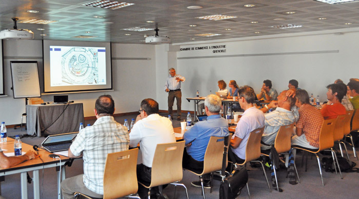
Following hot on the heels of Phase I, the year was especially important for the ASD as 1st January 2015 marked the start of the execution phase of the ESRF–EBS project. The project, approved by the ESRF Council in June 2014, will see the implementation of a new lattice for the storage ring to reduce the natural horizontal emittance from 4 nm to about 134 pm, thus greatly increasing the brilliance and coherence of the beam. The year saw a frenzy of activity in the division and great progress has been made. The project management team has grown with the addition of a new project assistant, procurement coordinator and installation officer, and a project planner is in the process of being recruited. Two ‘Accelerator Project Workshop’ events (see Figure 155) were held in July and November in order to review progress in the project, discuss future milestones and address any issues and actions to be taken. Discussion sessions spanned topics such as planning, risk analysis, safety aspects and resource requirements.
 |
|
Fig. 155: Accelerator physicist Dieter Einfeld discusses the assembly process with the accelerator project team during the first Accelerator Project Workshop. |
All efforts were put into a continuation of the intensive design work begun in 2014 and to start sending over 100 contracts out for tender, commencing with the most critical components or those longest to manufacture. Calls for tender have already been sent out for all of the magnets, including the sextupoles, octupoles, high-gradient and moderate-gradient quadrupoles, the dipole-quadrupoles and the permanent magnet blocks for the dipoles with longitudinal gradients and the correctors and mechanical parts for the longitudinal-gradient dipoles. In addition, a call went out for the stretched wire benches to take magnetic measurements. Calls for the girders for the storage ring were sent out in mid-December, with a delivery requested for the end of 2016. Concerning the vacuum chambers, calls were sent out for the high-profile stainless steel chambers and for the low-profile stainless steel chambers and the aluminium vacuum chambers. The execution phase will continue until October 2018, when the installation stage will begin. It will be overlapped by the pre-assembly of components, which will start in autumn 2017.
The work on the ESRF–EBS project was presented for review to the new Machine Advisory Committee on two occasions during 2015. The Machine Advisory Committee, or MAC, now chaired by Richard Walker of Diamond Light Source, replaced the Accelerator Project Advisory Committee, or APAC, after APAC chairman Dieter Einfeld’s appointment as accelerator physicist at the ESRF.
The first MAC meeting was held at the ESRF in April 2015. Over two days, work package leaders and other ESRF staff presented the progress of their work and, in particular, addressed the specific points raised at the last APAC. Following the event, the chairman complimented the project team on the significant technical progress made as well as the establishment of the definitive project organisation.
The second MAC meeting, in September, saw the panel of experts consider everything from the planning to the technical implementation and commissioning. The MAC was pleased to hear that the procurement of significant elements of the project such as the magnets and vacuum chambers was underway, and noted that a lot of work had been accomplished thanks to the strong support and motivation from all the ESRF divisions. Chairman Richard Walker emphasised that the project had made “great progress with no evident showstoppers foreseen!”
The ESRF also hosted the fifth Low Emittance Rings (LER) Workshop in September 2015, supported by the EuCARD-2* project (Enhanced European Coordination for Accelerator Research and Development). The goal of the workshop was to gather experts from the field of light sources, damping rings and colliders, to exchange their ideas, their results, and their future projects, demonstrating a remarkable example of open and friendly collaboration. The theme this year was beam dynamics and technological challenges for producing and controlling ultra-low emittance beams, and talks were given by individuals who have designed, commissioned and operated such rings. This was more than pertinent in view of the ESRF–EBS project!
P. Raimondi
Beam parameters of the storage ring
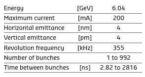
Table 1 presents a summary of the characteristics of the storage ring electron beam.
 |
|
Table 1: Principal characteristics of the electron beam. |
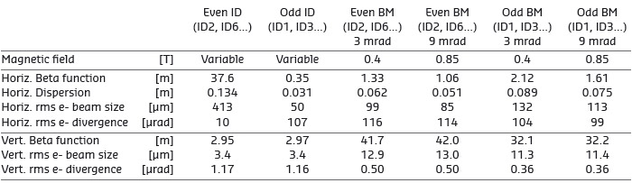
Table 2 gives the main optic functions, electron beam sizes and divergences at various source points. For insertion device source points, the beta functions, dispersion, sizes and divergences are calculated in the middle of the straight section. For bending magnets, two representative source points have been selected for each type of magnet (even or odd cell number), corresponding to magnetic fields of 0.4 T and 0.85 T. These points differ by the observation angles, of respectively 3 and 9 mrad from the entrance of the magnet.
 |
|
Table 2: Beta functions, dispersion, rms beam size and divergence at the various source points. |
Electron beam profiles are Gaussian and the size and divergence are presented in terms of rms values. The associated full width at half maximum sizes and divergences are 2.35 times higher. Horizontal electron beam sizes and divergences are given for the multibunch filling modes and apply to almost all filling patterns, except when the current per bunch is larger than 4.5 mA, for which a slightly larger size and divergence are attained because of the increased energy spread of the electron beam.
Vertical electron beam sizes and divergences are given for a vertical emittance of 4 pm, which is now the standard for 2 x 1/3 and 7/8+1 filling modes. The vertical sizes and divergences are about 1.4 times larger in uniform filling mode (due to ion effects, which are partially corrected by the use of a vertical bunch-by-bunch feedback). To increase the lifetime of the stored beam, the vertical beam sizes and divergences are deliberately increased by about a factor of 4 in the 16-bunch, 4-bunch and hybrid filling patterns.
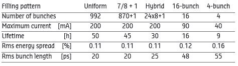
The lifetime, bunch length and energy spread mainly depend on the filling pattern. These are given in Table 3 for a few representative patterns. Note that in 16-bunch and 4-bunch filling patterns, the energy spread and bunch length decay with the current (the value indicated in the table corresponds to the maximum current). The bunch lengths are given for the usual radiofrequency accelerating voltage of 9 MV (8 MV for 16-bunch and 4-bunch).
 |
|
Table 3: Current, lifetime, bunch length and energy spread for a selection of filling modes. |
Summary of accelerator operation
With 5401 hours of beam delivered out of 5524 scheduled hours, the overall availability reached 98.53% compared to 99.11% in 2014. The lower availability is explained by four long failures that occurred in the first four runs of 2015: a problem with the master source, linked to ageing material and contamination of the network; a power supply fire, linked to ageing material and degradation of the insulation; leaking water hoses due to ageing; and dust particles clogging up the flowmeters and water filters in the cooling network. Also, in the first half of 2015, there was a higher than average number of arcs in the RF distribution system, solved by replacing a misplaced RF finger shield. For all these failures, proper corrective actions were taken in order to restart operation as soon as possible and avoid similar problems in the future.
The mean time between failures in 2015 reached 94 hours. The rate of failure was especially low during the last three runs, with only 21 failures over the last six months.
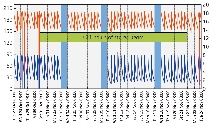
Failures aside, there were many excellent periods of unperturbed delivery in 2015, for example during November when beam was delivered without disturbance for 17 days (see Figure 156).
 |
|
Fig. 156: Uninterrupted beam delivery for 17 days (421 hours) in 7/8+1 and uniform filling modes during the run 2015-05. |
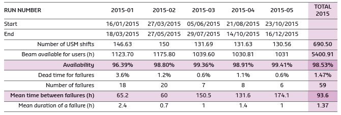
A summary of storage ring operation for the year is presented in Table 4.
 |
|
Table 4: Overview of storage ring operation in 2015. |
Filling patterns
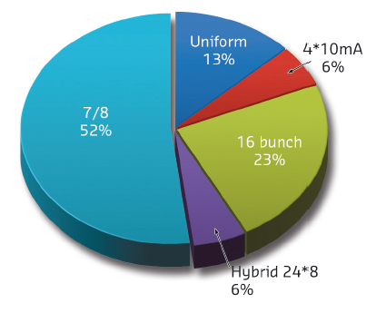
In 2015, a greater number of shifts were delivered in uniform mode (to the detriment of the 7/8 mode): 13% in 2015 compared with 5% in 2014. This represents five weeks of delivery for uniform mode compared to two weeks in 2014 (Figure 157). The distribution of delivery modes between 16-bunch, 4*10 mA and hybrid modes remains the same as in previous years.
 |
|
Fig. 157: Distribution of the various filling modes in 2015. |
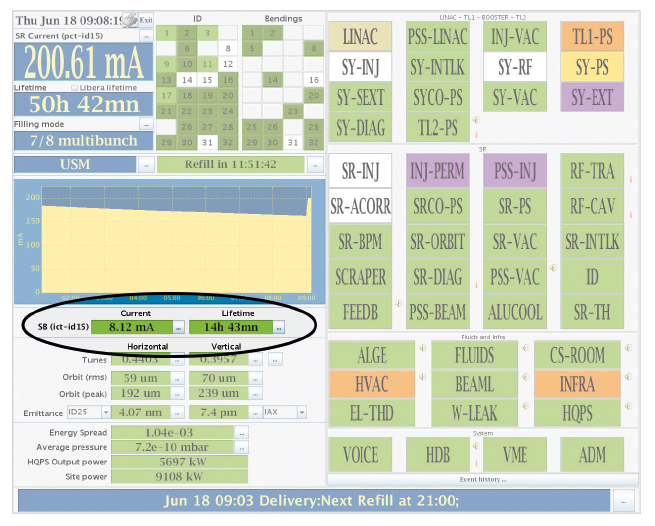
A noticeable improvement was made during the third run of 2015 when the single bunch intensity of the 7/8+1 mode was increased from 4 mA to 8 mA without any deterioration of other beam quality parameters such as emittance or lifetime (Figure 158). This was made possible thanks to the increase of the beam chromaticity coupled to a new optimisation algorithm of the lifetime. A similar increase of single bunch intensity was also done successfully during the delivery of the hybrid mode at the end of 2015.
 |
|
Fig. 158: Increase of the single bunch intensity to 8 mA in the 7/8 + 1 mode. |
Progress of the top-up project
In order to reduce the heat load variation of the beamline optics, the implementation of top-up has been under way over the past few years. This mode of operation will be initially beneficial for 16-bunch mode, and later for other filling patterns, by reducing the current variation and also by allowing delivery with low vertical emittance. The implementation of top-up has required development and modification of the machine in the following ways:
• Improving the reliability of the injector. Upgrades of the injector are close to being finalised (details below).
• Reducing or removing the vertical blow-up during the bunch cleaning process.
• Minimising the position stability disturbance during injection.
A feed-forward correction has been developed to limit the stability disturbance during injection and is now routinely used. Another correction system is used to minimise the effects of the septum field leakage.
Beam losses are being managed in order to allow injection with closed gaps. The gaps of the in-vacuum undulators are slightly open during the existing injection scheme to limit the beam losses and to avoid demagnetisation of the permanent magnets. In contrast, for top-up operation, the in-vacuum undulators will remain in their closed position. Simulations and experimental work was performed during 2015 to localise the losses on the scrapers.
An injection sequencer has been developed in order to automatically manage the equipment and to optimise electrical consumption. Using this tool, injection is now done in top-up in less than 30 seconds, including cleaning in the storage ring. The occurrence of the injection is communicated to the users using a software countdown system. It should be sufficient for most beamlines. An electrical signal could be provided to those who require a more precise gating of the data acquisition system.
User mode operation with the new hardware and a ‘top-up-like’ scheme is foreseen for the second run of 2016. In this run, the injection will continue with the standard sequence, but using the new hardware, timing sequence and bunch cleaning in the booster. User mode operation in top-up mode, starting with 16-bunch and 4-bunch modes, will commence thereafter, most likely during the third of run 2016.
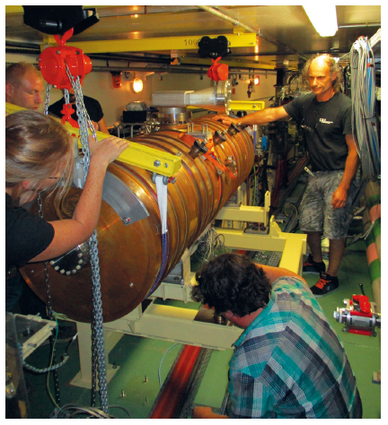
RF upgrade of the booster
Two additional five-cell cavities were installed in the booster in 2015 (see Figure 159). Instead of powering two cavities via two couplers per cavity, the four solid state amplifiers in the booster will now power one cavity each through a single power coupler. This will provide redundancy and therefore increase the reliability for top-up operation, as nominal operation parameters can already be achieved with just three units in operation. With all four systems in operation, only half the power is required to obtain the same acceleration as compared to the former two-cavity system, and at maximum power, a 40% higher peak RF voltage is generated.
 |
|
Fig. 159: Members of the RF group manage the tricky installation of two five-cell cavities in the booster. |
Linac upgrade
The refurbishment of the Linac, undertaken within Phase I of the ESRF Upgrade, has reached completion. In 2015 a new buncher cavity was installed and commissioned in the Linac and the initial buncher will now serve as a spare. In parallel, a third klystron modulator was built in house and commissioned to serve as a hot spare and safeguard operation in case of a major modulator failure. Today, some problems of arcing in the klystron output waveguide still need to be solved before this modulator becomes operational for the start of top-up operation in 2016.
Bunch cleaning in the injector
Currently, for the various filling patterns, the unwanted electrons in nominally empty buckets of the storage ring are systematically removed after each injection by means of a selective resonant excitation that also slightly perturbs the stored beam. To avoid this disturbance for the planned top-up operation, the bunch purity will be established first in the injector.
For this purpose, two approaches have been envisaged. A prototype fast stripline kicker has been successfully implemented, allowing the injection of only one bunch from the Linac and without a single spurious electron that could pollute adjacent buckets. The booster extraction still needs to be optimised to avoid tiny portions of the bunch tails being extracted before the fast extraction kicker is fired, when the slower extraction bumps are already being raised.
The second possibility is to perform bunch cleaning in the booster and the necessary hardware for this was installed during the 2015 winter shutdown. Many tests have been carried out showing the potential of this system. Nevertheless, the present stability and reproducibility of the booster power supply does not allow this system to be used in routine operation. Once operational, the new booster power supply should provide the required stability.
New beam position monitor electronics in booster and TL2
In March 2015, the 75 BPMs in the booster were all equipped with new Libera Spark electronics that have a greatly improved performance and functionality range. The tests and commissioning after the installation went very smoothly. In addition to X and Z position measurements, the system offers the possibility of monitoring the booster beam current with a high level of sensitivity and reproducibility. This in itself allows sensitive measurements to be made of the transfer efficiency of the booster current to the storage ring. Results of the first tests look very promising and a complete and routine application for serving this purpose is in progress.
In addition, the Spark electronics have been further developed and enhanced in collaboration with the manufacturer to serve other purposes such as position measurements and relative charge measurements in Transfer Line 2 (TL2) and seven BPMs are now in place. Concerning the extra BPMs for the EBS project, further improvements on resolution, precision and reproducibility of the Spark device have been tested on prototypes that carry adapted firmware versions. The tests performed so far confirm their full compatibility with the defined requirements.
New booster power supplies
A new booster ramped injection power supply (RIPS) operating at 4 Hz has been developed and is now under procurement and testing. Two dipole inverters will be delivered in March 2016 after successful factory acceptance tests. Tests of the dipole inverters and rectifiers, then of the whole RIPS system will follow in early 2016. The full cabling scheme is nearly complete and full power tests will be carried out after installation. Tests of the User mode operation with the new RIPS is foreseen for the second run of 2016, with operation in top-up mode commencing shortly thereafter. New power supplies for the septum magnets have also been installed.
In 2015, the power for each magnet was optimised to have a minimum number of different power converter units and preparations are being made for hot-swapping capabilities. The characteristics of the DC common source network distribution are ready to be finalised following the evaluation of the DC-DC converter prototypes for the ESRF–EBS. The first estimation of the cross section of power cabling within the core of the girders has been proposed and will be refined during 2016.
ID straight sections
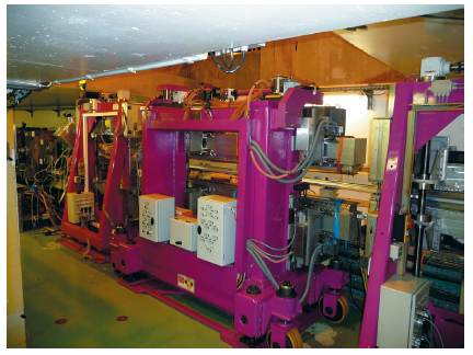
ID32 was completed with the installation of a new 2.5 m-long helical undulator in the straight section in May 2015 (see Figure 160). A high-performance cryogenic permanent magnet undulator, due to be installed on ID31 at the end of 2015, will be postponed until summer 2016. Work to modify the ID15 straight section with a canting scheme has been carried out during the year. A required short, high-field wiggler has been designed and the associated components have been procured. The modification of the straight section and a new insertion device layout (a U22 in-vacuum device upstream and, later in summer 2016, an IVU-20 downstream) will be completed in 2016.
 |
|
Fig. 160: The new 2.5 m-long helical undulator, installed on ID32, produces circular polarisation rather than only horizontal plane polarisation like most undulators. |
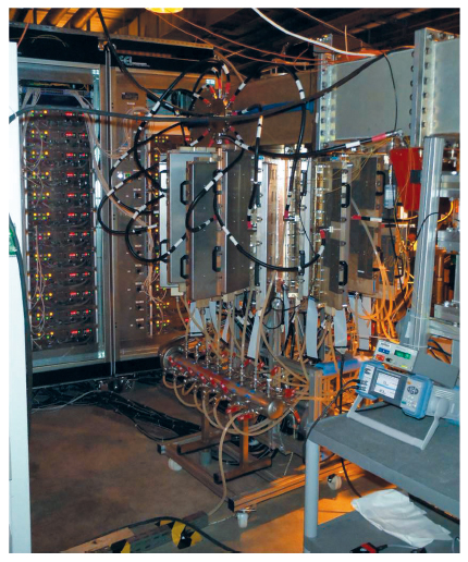
75 kW from a compact in-house RF solid state amplifier
The prototype radiofrequency solid state amplifier (see Figure 161) uses a cavity combiner to combine the power from 132 ESRF-developed fully planar 700W RF power modules. This SSA has now been tested successfully and in December 2015 the design RF power of 75 kW was reached with 61% DC-to-RF conversion efficiency. Further development should permit the total output power to be increased.
 |
|
Fig. 161: The prototype solid state amplifier could eventually become the basis for a replacement of obsolete klystron transmitters. |
partners


European Synchrotron Radiation Facility - 71, avenue des Martyrs, CS 40220, 38043 Grenoble Cedex 9, France.