- Home
- Aharonov-Bohm interferences from local deformations in graphene
Aharonov-Bohm interferences from local deformations in graphene
Since graphene was first isolated in a controlled way, it has been an optimal playground to test the most exciting ideas in condensed matter. Its curvature and elastic deformations can be modelled by means of fictitious gauge fields as if the system were in the presence of a magnetic field [1]. These fields have become an experimental reality after the observation of strain-induced Landau levels in graphene with effective fields up to 300 T [2]. We have theoretically explored the opposite (low-field) geometrical limit, where the electronic excitations can still be described in terms of plane waves rather than Landau levels. In particular, we have discussed a realisation of the Aharonov-Bohm effect due to mechanical deformations in graphene that can be used to detect stresses at the nanometre scale.
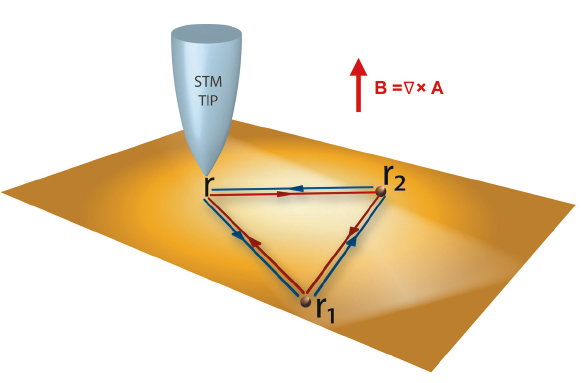
The Aharonov-Bohm effect is one of the hallmarks of quantum physics, widely established as the textbook illustration to explain the physical content of the electromagnetic gauge fields [3]. In the context of quantum transport in meso- and nanoscopic devices, in particular, it was found that the Aharonov-Bohm effect gives rise to a peculiar magnetoresistance behaviour due to the specific way in which it touches on the phenomenon of weak localisation [4]. More recently, a scanning-tunnelling-microscopy (STM) setup has been put forward to visualise directly the Aharonov-Bohm effect through oscillations in the local density of states (LDOS) [5]. The STM is a very convenient tool for studying the properties of the 2D electron gases that form at the close-packed surfaces of noble metals such as Cu(111) or Ag(111), where the proposed Aharonov-Bohm setup can easily be implemented. The main idea is to replace the open electron paths of the standard Aharonov-Bohm interferometers by the closed loops depicted in Figure 72. Thus, in the presence of a time-reversal symmetry-breaking gauge field, electrons scattering along these loops pick up different phases depending on whether the scattering is clockwise or anticlockwise. This further affects the interference contribution to the LDOS measured by the STM tip, which eventually exhibits oscillations as a function of the magnetic flux. More specifically, the LDOS can be written as N = N0 + Nloop [cos (πΦ/Φ0) - 1], where N0 is the LDOS in the absence of the gauge field, Nloop is its interference contribution along the loops, Φ is the magnetic flux through the area enclosed by the loop, and Φ0 is the flux quantum. This simple setup can be of potential use to detect space variations of the magnetic field at the nanometre scale as discussed in [5].
 |
|
Fig. 72: Sketch of the STM Aharonov-Bohm interferometer proposed in [5]. |
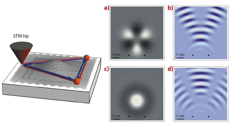
In the case of graphene, electrons are described by an effective Dirac Hamiltonian that can be derived from a microscopic tight-binding model. Then, when the graphene sheet deforms, and the tight-binding parameters change accordingly, the effective Hamiltonian becomes H = - i![]() vF σi (∂i - iAi), where the effective gauge field A traces back to the change of the electron hopping with the lattice deformations [A = (kΦ0/π) (uxx - uyy, - 2uxy), with uij being the strain tensor] [1]. This brings out the possibility of having Aharonov-Bohm interferences without real magnetic fluxes since, in the case of graphene, having a certain landscape of deformations is analogous of having the system in the presence of a magnetic field. The emergent gauge field A, however, preserves time-reversal symmetry and therefore seems to give no net Aharonov-Bohm effect. In reality, in each of the two different Dirac points, the electrons feel an effective symmetry breaking that is restored only once the system is considered as a whole (because the coupling with the gauge field has opposite signs in the two different Dirac points). As long as the two Dirac points are independent, this suffices to generate Aharonov-Bohm interferences in the LDOS as we have demonstrated in [5]. The result is illustrated in Figure 73, which shows that the above STM setup can also be used to probe tiny deformations of graphene sheet by means corresponding Aharonov-Bohm oscillations.
vF σi (∂i - iAi), where the effective gauge field A traces back to the change of the electron hopping with the lattice deformations [A = (kΦ0/π) (uxx - uyy, - 2uxy), with uij being the strain tensor] [1]. This brings out the possibility of having Aharonov-Bohm interferences without real magnetic fluxes since, in the case of graphene, having a certain landscape of deformations is analogous of having the system in the presence of a magnetic field. The emergent gauge field A, however, preserves time-reversal symmetry and therefore seems to give no net Aharonov-Bohm effect. In reality, in each of the two different Dirac points, the electrons feel an effective symmetry breaking that is restored only once the system is considered as a whole (because the coupling with the gauge field has opposite signs in the two different Dirac points). As long as the two Dirac points are independent, this suffices to generate Aharonov-Bohm interferences in the LDOS as we have demonstrated in [5]. The result is illustrated in Figure 73, which shows that the above STM setup can also be used to probe tiny deformations of graphene sheet by means corresponding Aharonov-Bohm oscillations.
 |
|
Fig. 73: (Left panel) Proposed STM setup for measuring Aharonov-Bohm oscillations due to deformations in graphene. (Right panels) Distribution of pseudo magnetic fields generated by (a) out-of-plane Gaussian bump and (c) in-plane displacements with C3 symmetry, and corresponding patterns of Aharonov-Bohm oscillations in the LDOS (b and d respectively). The black dots indicate the position of the scatterers. |
Principal publication and authors
F. de Juan (a), A. Cortijo (b), M.A.H. Vozmediano (c) and A. Cano (d), Nature Phys. 7, 810 (2011).
(a) Department of Physics, Indiana University, Bloomington (USA)
(b) Departamento de Física Teórica, Universidad Autónoma de Madrid (Spain)
(c) Instituto de Ciencia de Materiales de Madrid (CSIC) (Spain)
(d) ESRF
References
[1] M.A.H. Vozmediano, M.I. Katsnelson and F. Guinea, Phys. Rep. 496, 109-148 (2010).
[2] N. Levy et al., Science 329, 544-547 (2010).
[3] Y. Aharonov and D. Bohm, Phys. Rev. 115, 485 (1959).
[4] G. Bergmann, Phys. Rep. 107, 1 (1984).
[5] A. Cano and I. Paul, Phys. Rev. B 80, 153401 (2009).
partners


European Synchrotron Radiation Facility - 71, avenue des Martyrs, CS 40220, 38043 Grenoble Cedex 9, France.