General description
BM01 and BM31 S w i s s - N o r w e g i a n CRG
DIFFRACTION AND ABSORPTION SPECTROSCOPY
General purpose beamline with two experimental stations that are operated fully independent
Scientific applications:
Experimental Hutch 1 (BM31): powder diffraction, EXAFS, and white beam topography
Experimental Hutch 2 (BM01): single-crystal diffraction, small molecules and macromolecular crystallography.
Optics for BM31:
|
|
|
|
|
|
|
|
|
|
Optics for BM01:
| Optical elements | Mirror 1 | Double-crystal mono. | Mirror 2 |
| Distance from source | 25.9m | 28.5m | 30.8 m |
| Focusing type | Rh coated
Vert. collim. |
Si (111)
Sagittally focusing |
Rh coated
Vert. focusing |
| Beam size at sample | Nominally 0.5 x 0.5 mm2 FWHM focused | ||
| Spectral range | 6 - 22 (30) keV | ||
| Horizontal acceptance | 2 mrad | ||
Introduction
The beamline is designed as a general purpose line with two experimental stations, BM01 and BM31. BM31 is designed for powder diffraction, EXAFS and white-beam topography experiments, while BM01 caters for high resolution single-crystal diffraction on inorganic structures and small molecules, and for macromolecular crystallography.
Beamline Design and General Layout
The beamline is installed on a bending magnet source (dipole BM01). The incoming beam is divided in a splitter vessel into two separate beams. These beams are delivered to their respective experimental stations which can be operated independently (e.g. separate radiation shutters allow simultaneous operation of both stations with unrestricted access). A 1 mrad fan of radiation is send directly into the first experimental hutch (BM31) situated 10 m downstream with respect to the splitter-vessel. A water-cooled, Si (111)channel cut is positioned after a cooled Be-window inside BM31. Immediately after the vacuum chamber of the monochromator a cooled beamstop prevents the white beam from entering further into the hutch. However, this beam-stop can be removed for white beam experiments. A further set of horizontal and vertical slits defines the beam cross-section (either monochromatic or white beam) which passes through a final Be window before it reaches the sample.
On the other side of the beamline, a 2 mrad fan of radiation will first be vertically collimated by a primary mirror. The mirror angle relative to the incident beam is adjustable, but will be nominally set at 3 mrad. With the Rh coating on the silicon mirror, this angle of incidence leads to an energy cut-off at about 24 keV. Reflection from this mirror will produce a highly parallel beam incident on a double crystal monochromator, enabling both high throughput and narrow energy resolution to be achieved. The first crystal of the monochromator will be water cooled, while the second crystal will be sagittally bent for horizontal focusing. A variable gap between the two crystals, combined with a translation of the second crystal along the beam direction, allows a constant beam exit height to be maintained. Alternatively, a flat second crystal can be mounted in place of the sagittally bent crystal, for experiments requiring high resolution, parallel beam optics. Fixed, cooled Be windows are mounted immediately before and after the monochromator vessel. A fixed beam-stop positioned after this vessel intercepts the white beam and Bremsstrahlung radiation. This beam-stop may not be removed, and is integrated into the Personnel Safety System (PSS). An adjustable beam-stop is also available to intercept the white beam reflected from the first mirror. Finally a secondary mirror, identical to the first mirror, provides vertical focusing at the sample in the second hutch (BM01). Between each of the optical elements (mirror - monochromator - mirror) a slit vessel is installed which contains a set of motorised, horizontal and vertical slits. These function both as anti-scatter slits and beam collimators. A final set of motorised horizontal and vertical slits is installed at the end of the vacuum line inside the experimental hutch. A Be scatter foil and a scintillation counter mounted immediately in front of the exit window are used to monitor the beam intensity.
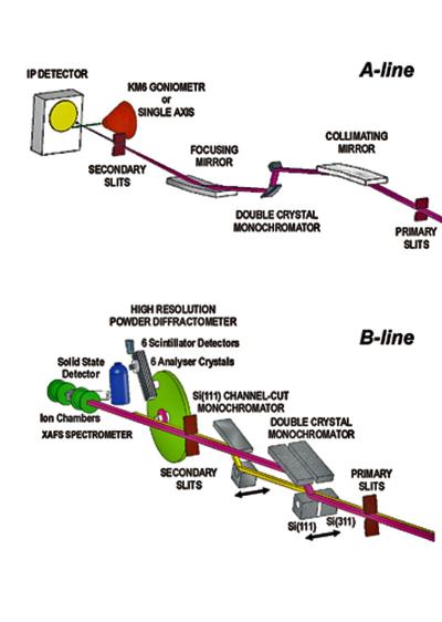
Fig. BM01 and BM31
Schematic layout of the Swiss-Norwegian beamline
The beamline is designed so that operation with or without the mirrors is possible. The general layout of the optics enclosure as well as Station BM31 and Station BM01 is shown in the Figure. Separate data acquisition cabins are available for the controling of the experiments conducted in each station. These cabins also contain the beamline vacuum control system. A sample preparation cabin is situated at the end of the beamline. In addition, laboratory-, office space and a small workshop are now available in a new building adjacent to the beamline.
Experimental equipment
The design of the experimental hutches and the available equipment access (via roof hatches and sliding doors) allow a large variety of experimental equipment to be installed. The choice of appropriate station (focused or unfocused, monochromatic or white beam) depends upon the specifications of the individual experiment. A general purpose, motorised experimental bench (1.0 x 0.7 m2 surface) is available in each station.
The following apparatus are on the beamline:
Single-crystal diffractometer
A single-crystal diffractometer (KUMA KM6-CH) is available for small molecule crystallography. A suitable arrangement of circles allows a wide variety of scanning techniques to be employed. The rotary tables can support sample chambers weighing up to 20 kg (furnaces, cryostats, pressure cells, etc.). The machine is temporary unavailable.
Multipurpose PILATUS@SNBL diffractometer
The diffractometer is based on PILATUS2M detector, it combines advantages of pixel area detector with flexible goniometry and easy re-positioning of the detector in vertical and horizontal directions. The diffractometer can be used for single crystal, powder, and thin film diffraction experiments.
Powder diffractometer
A robust 2-circle diffractometer is available for high resolution powder-diffraction measurements. Each circle has a high precision encoder mounted directly on the rotary axis. The diffractometer is currently equipped with 6 counting chains, meaning that 6 complete patterns are collected simultaneously, with an offset in 2-theta. The angular offset between the detectors has been kept to very small (~1.1 deg) in order to keep the total data collection time to a minimum. An Si-111 analyzer crystal is mounted in front of each detector (Na-I scintillation counter), resulting in an intrinsic resolution (FWHM) of approx. 0.01 deg at a wavelength of 1Ã . The available wavelength range for the instrument is 0.4 to 1.2 Ã . Transmission (capillary) measurements can be perfomed between 5 and 1273 K. A flat plate sample spinner as well as a texture attachment can be mounted. Avalable on the beamline are thus a Janis He cryostat for temperatures between 4 and 350 K as well as a furnace that covers the range from roomtemp up to 1000 C. The environment in the furnace can be controlled with both oxidizing and inert atmospheres.
EXAFS spectrometer
A general purpose X-ray absorption spectroscopy set up is available at the SNBL. The monochromator, a Si-111 channel-cut type, provides a wide energy range from 6 to 41 keV. Alternatively measurements can be performed on the first harmonic to measure at higher engergies or with a higher energy resolution. A 311 monochromator will be available in the future. Harmonic rejection is performed by a double-bounce gold or chromium coated mirror system. A single-element solid-state detector is available for fluorescent EXAFS studies. A multi element detector is also foreseen but not available yet. Transmission, fluorescence and reference data can be measured in parallel on the six available counting channels.
White-beam topography camera
A camera for white-beam topography measurements consisting of a fast shutter, sample-aligment stage and a mount for X-ray film or nuclear emulsion plate will be installed on a motorised experimental bench in the white-beam hutch (BM31). The beam cross-selection incident on the sample is defined by the water-cooled slits positioned immediately before the exit Be-window. Either He-filled or evacuated beam tube may be required along the beam path within the station, to reduce the generation of ozone by the white beam.
partners


European Synchrotron Radiation Facility - 71, avenue des Martyrs, CS 40220, 38043 Grenoble Cedex 9, France.