- Home
- Users & Science
- Scientific Documentation
- ESRF Highlights
- ESRF Highlights 2012
- Accelerator and X-ray Source
- Fast orbit correction system
Fast orbit correction system
One of the defining features of a third generation light source is an electron beam with an extremely low emittance. Experiments can only take advantage of the resulting small spot size on the sample if the orbit of the electrons in the storage ring is stable within a fraction of the photon beam size. To achieve the required stability, beam position monitors (BPMs) located around the storage ring take data and calculate an orbit correction which is then applied by way of a set of corrector magnets. The present version of the ESRF’s beam orbit correction system, implemented in 2009, uses 224 BPMs equipped with new Libera Brilliance electronics and 96 corrector magnets. This set-up provides a position resolution of a fraction of a micrometre compared to several micrometres using the electronics implemented in 1992. However, today’s experiments demand even higher beam stability. In particular, a major cause of orbit distortion is the frequent modification of insertion device parameters, such as gap and phase changes due to increasingly creative ways of operating the beamlines.
In May 2012, the ESRF orbit correction system was restarted with the implementation of the following new items:
- A new set of wide-band power supplies enabling the 96 corrector magnets to be driven with a bandwidth of 500 Hz.
- A fast data network able to broadcast the position data measured by the Libera modules (and the corresponding correction kick data) over the full system at a rate of 10 kHz via a network of optical fibres that link the Libera crates and all the power-supply controllers. The protocol managing this data flow, the “communication controller”, was developed at the Diamond Light Source and the 10 KHz position data generation is a standard feature of the new Libera Brilliance electronics.
- Eight power-supply controllers connected to the communication controller and to the data ports of the power supplies. These units are equipped with powerful FPGA digital signal processors that compute, every 100 µs, a new set of correction kicks derived from the position data.
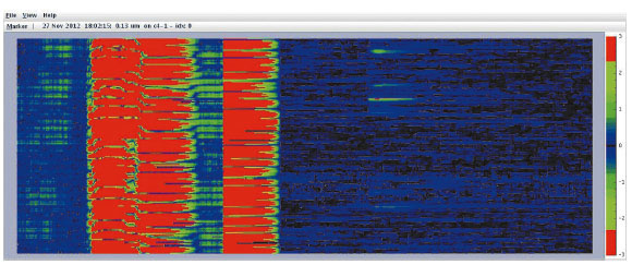
Due to this upgrade, the storage ring orbit distortion is now damped with a bandwidth going from DC up to 150 Hz, as before, but with the addition of an accurate fast correction at the location of every BPM. Figure 148 shows the gain in stability from using the new system while closing the ID gaps following injection.
 |
|
Fig. 148: ESRF electron beam stability measured with the 224 BPMs of the orbit correction system over the whole storage ring while closing the ID gaps following injection. The horizontal axis shows time – a total of 15 minutes. The vertical axis shows the readings of the 224 BPMs. On the left, beam movements with a correction every 10 seconds, as was the case until May 2012; On the right, beam movements during the same sequence of ID gap changes, using the fast orbit correction system commissioned in May 2012. The orbit corrections are now applied in a bandwidth ranging from 0 Hz to 150 Hz. |
For the users, the crucial difference will be to render unnoticeable the effect of the transient parasitic kicks that occur during the change of parameters of some insertion devices. These transient parasitic kicks have been one of the biggest sources of instability in the source over the last few years. Before the beam orbit correction upgrade, vertical steps of more than 5 µm could be observed over the two cells surrounding some badly corrected insertion devices. Now, recent tests have demonstrated stability of the beam position in the vertical plane better than 200 nm over the 0.1 to 100 Hz frequency range at all points around the storage ring.
In addition, this new system is expected to provide a powerful diagnostics tool. It will allow us to measure and correct imperfections of the ring lattice and to tune the storage ring optics in order to deliver beam with record low emittance in the near future.
partners


European Synchrotron Radiation Facility - 71, avenue des Martyrs, CS 40220, 38043 Grenoble Cedex 9, France.