- Home
- Hard X-ray interferometer based on a silicon refractive bi-lens system
Hard X-ray interferometer based on a silicon refractive bi-lens system
Optical interferometers are widely used for diagnostics and metrology because of the availability of lasers with a high degree of spatial coherence. X-ray interferometry, however, has long been hampered by the lack of coherent sources. To circumvent this problem, the first X-ray interferometers used the so-called perfect crystal optics in the regime of dynamical diffraction. Due to the coherent interaction of the X-rays with a three-dimensional crystal structure, the crystal becomes an intrinsically coherent device and therefore does not require spatial coherence of the incident radiation. The classical example is the Bonse-Hart interferometer, which utilises both transmission (Laue) and surface reflection (Bragg) diffraction components.
Nowadays, the widespread availability of bright X-ray sources with sufficiently large spatial coherence, such as third-generation synchrotrons, allows researchers to observe interference by division of the wave front, similar to the classical Young’s experiment. Recently a Fresnel double slit, a Fresnel double prism and a Fresnel double mirror were applied to measure the spatial coherence of synchrotron beams.
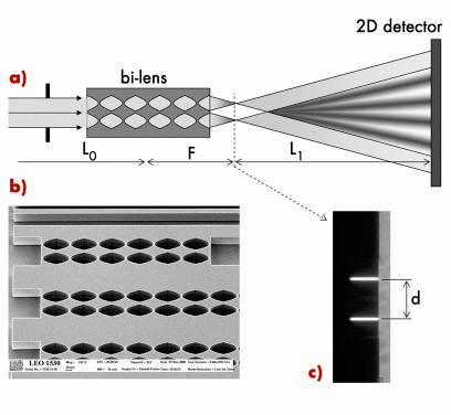
Following the successful development and application of refractive optics for high energy X-rays [1,2], we have constructed an X-ray bi-lens interferometer similar to the Billet split lens in classical optics. The schematic diagram of our X-ray bi-lens interferometer is shown in Figure 158. It consists of two identical parallel planar compound refractive lenses (CRLs) separated by a certain distance, d. Each lens produces an image of the source. When the lens split distance d is smaller than the spatial coherence length of the incoming beam, these images are diffraction limited and can be treated as coherent secondary sources. At a distance of more than twice the lens focal distance, F, the radiation cones diverging from these coherent secondary sources overlap, and interference occurs in the region of superposition (see Figure 158). Identically to the Fresnel double slit, the visibility (or contrast) of the recorded interference pattern can be used as a measure of the degree of a spatial coherence of the incident beam, or of an equivalent effective source size.
A silicon chip with a set of different linear (1D) bi-lenses was manufactured using semiconductor microfabrication technology (Figure 158b). The length of each single, individual lens was 100 µm and the aperture was 50 micrometres. The radius of the parabola apex was 6.25 µm. The compound refractive lenses were separated by a distance d = 60 µm.
The bi-lens interferometer was tested at beamline ID06. The liquid -nitrogen cooled Si-111 double crystal fixed exit monochromator (manufactured by CINEL, Italy) was used at an X-ray energy of 12 keV. The Si bi-lens chip was mounted on the microoptics test bench optics stage at a distance L0 = 55 m from the source. All measurements of bi-lens interference patterns were made in a vertical plane. The interference patterns were recorded by means of the high resolution X-ray CCD Sensicam camera with a spatial resolution about 1.3 µm (0.645 µm pixel size). The typical exposure time was 5-10 sec. during 16-bunch filling mode.
 |
|
Fig. 158: a) Schematic drawing of the experimental set-up used for the bi-lens test. b) Scanning electron microscope micrograph showing a fragment of silicon bi-lenses chip. c) Image of the bi-lens foci recorded at a distance F = 35 mm shows the lenses split distance d = 60 µm. |
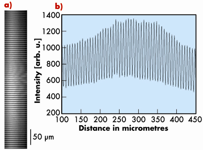
The observed interference pattern is shown in Figure 159. The fringe spacing or peak-to-peak width of the fringes is given by ![]() =
= ![]() L1/d, where
L1/d, where ![]() is the wavelength, and L1 is the distance from the bi-lens focus plane to detector plane. The measured spacing,
is the wavelength, and L1 is the distance from the bi-lens focus plane to detector plane. The measured spacing, ![]() = 6.25 µm, is in very good agreement with calculations. The quality of the fringes produced by a bi-lens system can be described quantitatively using the visibility V = (Imax– Imin)/ (Imax + Imin), where Imax and Imin are the irradiances corresponding to the maximum and adjacent minimum in the fringe system. It is easy to show that the visibility V is directly related to the source size, S, as follows:
= 6.25 µm, is in very good agreement with calculations. The quality of the fringes produced by a bi-lens system can be described quantitatively using the visibility V = (Imax– Imin)/ (Imax + Imin), where Imax and Imin are the irradiances corresponding to the maximum and adjacent minimum in the fringe system. It is easy to show that the visibility V is directly related to the source size, S, as follows:
![]()
The measured visibility was close to 40%, corresponding to an effective source size in the vertical direction of about 45 µm (FWHM).
The bi-lens interferometer presented here has major advantages over existing methods. Manufacturing of micro-slits, mirrors and prisms for hard X-rays is a challenging technological task considering the requirements to the surface and shape (edges) quality. Whereas for silicon planar lenses, the well-developed microelectronics technology is used providing superior lens quality [3]. Compared to slits, mirrors and prisms, the compound refractive bi-lens system can be used at high photon energies up to 100 keV.
 |
|
Fig. 159: a) Interference pattern obtained using the bi-lens interferometer of Figure 158, recorded at a distance 4 m with monochromatic beam at energy E = 12 keV. b) Intensity variation for a line through the centre of the fringe pattern shows a visibility (contrast) of approximately 40% corresponding to a source size S = 45 µm vertically (FWHM). |
The applications of the bi-lenses are not limited to coherence characterisation. They can easily be extended to coherent imaging techniques. As with a classical interferometer, the bi-lens interferometer generates two coherent beams separated in space and then coherently recombines them producing the interference pattern. One can easily insert a sample into one of the beams while they are separated. Any interaction with the beam would then induce significant changes in the interference pattern. From the new phase pattern, one should then be able to extract information concerning the nature and degree of interaction of the sample with the beam, leading, eventually, to a holographic reconstruction of the sample.
Authors
A. Snigirev (a), V. Kohn (b), I. Snigireva (a), M. Grigoriev (c), S. Kuznetsov (c), V. Yunkin (c), T. Roth (a), C. Detlefs (a) and G. Vaughan (a).
(a) ESRF
(b) Kurchatov Instititute, Moscow (Russia)
(c) Institute of Microelectronics Technology, Chernogolovka (Russia)
References
[1] A. Snigirev, V. Kohn, I. Snigireva, B. Lengeler, Nature 384, 49 (1996).
[2] V. Aristov, M. Grigoriev, S. Kuznetsov, L. Shabelnikov, V. Yunkin, T. Weitkamp, C. Rau, I. Snigireva, A. Snigirev, M. Hoffmann, E. Voges, Appl. Phys. Lett. 77, 4058 (2000).
[3] A. Snigirev, I. Snigireva, M. Grigoriev, V. Yunkin, M. Di Michiel, S. Kuznetsov, G. Vaughan, SPIE 6705, 670506-1 (2007).
partners


European Synchrotron Radiation Facility - 71, avenue des Martyrs, CS 40220, 38043 Grenoble Cedex 9, France.