- Home
- Grain mapping of stress corrosion cracks by diffraction contrast tomography
Grain mapping of stress corrosion cracks by diffraction contrast tomography
Stainless steels can suffer from intergranular stress corrosion cracking in certain conditions. Damage occurs via the nucleation and growth of cracks by localised corrosion of susceptible, sensitised grain boundaries under the action of stress. It is a potential failure mechanism in some power station components, where sensitisation can result from heat treatments, or fast neutron irradiation [1]. The susceptibility of grain boundaries to sensitisation depends on their structure at the atomic level, which depends on the relative crystal orientations of the grains at the boundary, as well as the orientation of the boundary relative to the grains. Certain special boundaries resist sensitisation, and previous experiments at the ESRF have shown that these resistant boundaries can form bridges across the advancing crack [2], increasing the resistance to stress corrosion cracking [3]. Hence, grain boundary engineering aims to improve material performance by maximising the fractions of resistant boundaries [4].
Diffraction contrast tomography (DCT) is a technique recently developed at the ESRF for mapping 3D grain shape and orientation in polycrystalline materials [5]. A technique related to the ID11 3D X-ray microscope project, DCT combines microtomography with an analysis of the diffraction spots arising from grains in the sample. As well as work reported here, other current research projects are using DCT to investigate the growth of grains during annealing, the interaction of fatigue cracks with microstructures, and on the distribution of strains and stresses in elastically anisotropic materials.
 |
|
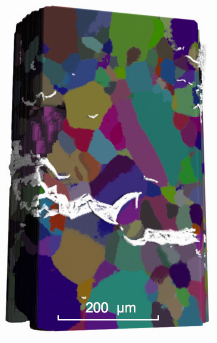
Fig. 137: Part of the DCT grain map of a stainless steel sample, combined with the crack path (shown in white). |
In the stress corrosion cracking project, DCT was used to map the grain structure of a sensitised stainless steel sample (Figure 137). This revealed the crystallographic orientation of the grains on either side of each boundary, as well as the orientation of the grain boundary planes, which provides the required full macroscopic description of grain boundary structure. Because DCT is a non-destructive technique, the sample was then available for a subsequent in situ stress corrosion cracking investigation using standard microtomography. Both the grain mapping and in situ cracking observations were made using beamline ID19. We were able to align the crack path with the grain boundaries as shown in Figure 137, and thus associate bridges across the crack with particular grain boundaries (Figure 138). We could then examine the structure of these special grain boundaries, and compare them to the population of grain boundaries in the sample (~1600 boundaries in total) and also to the subset of grain boundaries that failed by stress corrosion cracking.
 |
|
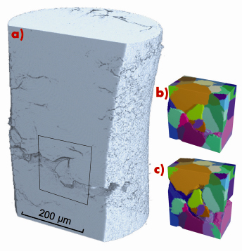
Fig. 138: a) A bridge across the crack, b) a rendering of the grains around this feature, and c) the grains with the crack opening displacements applied. |
In conclusion, diffraction contrast tomography was used to map the grain shapes and orientations in a polycrystalline stainless steel sample, revealing the crystallographic character of the grain boundaries. We could then grow an intergranular stress corrosion crack in the sample, and make in situ tomographic observations of how the crack interacted with the microstructure, revealing which boundary types tend to resist crack propagation.
Principal publication and authors
A. King (a,b), G. Johnson (a,b), D. Engelberg (a), W. Ludwig (b,c) and J. Marrow (a), Science 321, 382 (2008).
(a) Manchester University (UK)
(b) ESRF
(c) MATEIS, INSA de Lyon (France)
References
[1] P.M. Scott, Corrosion 56, 711 (2000).
[2] L. Babout et al., Mater. Sci. Technol. 22, 1068 (2006).
[3] A.P. Jivkov, T.J. Marrow, Theoret. App. Fracture Mechanics 48, 187 (2007).
[4] D.L. Engelberg, R.C. Newman, T.J. Marrow, Scripta Mat. 59, 554 (2008).
[5] G. Johnson et al., J. Appl. Crystallogr. 41, 310 (2008).
partners


European Synchrotron Radiation Facility - 71, avenue des Martyrs, CS 40220, 38043 Grenoble Cedex 9, France.