- Home
- Users & Science
- Find a beamline
- ID19 - Microtomography beamline
- ID19 Beamline description
- Experimental Hutch
- How to use stroboscope
How to use stroboscope
electronics done by François Thurel, mechanics by René Chagnon, software by David Fernandez Carreiras, written by Petra Pernot
This "section topograph" stroboscopic shutter can be used for frequencies from 1 to 40 Hz. The corresponding experimental set-up is shown on figure 1.
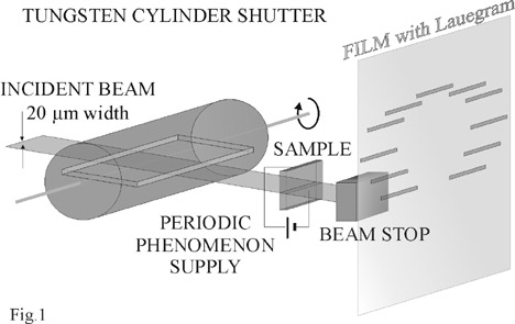
The slit can be placed also behind the stroboscope just before the sample. The shutter consists of a tungsten cylinder with a fixed thin slit along its 16 mm long diameter. Various slit apertures have been drilled in different cylinders: 1 mm, 0.5 mm and 0.25 mm. The cylinder is rotated using a step-by-step motor. An encoder fixed on the motor delivers an electric signal equal to half of the stroboscope frequency. This reference signal is then transformed according to the experiment and depending on the sample, and is shifted as a function of the investigated moment of the period. The main advantage of this stroboscope is related to its mechanical simplicity. Mechanically induced jitters are reduced, and the time precision achieved is better than 1% of the period. The stroboscope has to be placed in the blue box of the Experimental hutch on the HMONO goniometer. Both vertical and horizontal attachment (i.e. vertical or horizontal sections) are possible accordingly to the demand of a given experiment. The real view of the installed stroboscope is on fig.2.
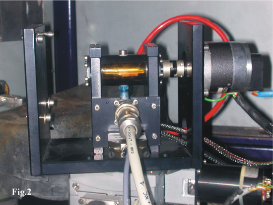
The motor and encoder cables are visible as well as the red tube delivering the Nitrogen gas which keeps the slit reasonably clear.
The "strobo" motor is defined in HDIFFR, having 400 steps per turn, i.e. per 360 degrees. Its 'steady state rate' in config define the speed of the motor and consequently the stroboscopic frequency. Example: if equal to 400, the motor speed is one turn per second, two stroboscopic pulses (slit passes twice in one turn) are delivered. Corresponding DPAP2 is located in 04 cupboard in the bottom rack, DPAP2 is second from the left, fig.3. The DPAP2 current should be BB0 and no limit switches set.

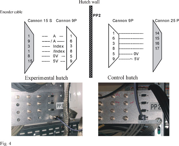
The encoder has 500 steps per turn, i.e. per 360 degrees. It delivers signal each time the index passes (once per turn). The encoder cable description with the real connection in the Experimental and Control hutch respectively on PP2 panel are shown in fig.4.
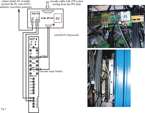
The encoder cable enter on the "Add On" carte, mounted on the "Line Driver" carte, which generates a pulse on the leading edge of EITHER of the signals of Gate Out 1 and 2 from VCT6 carte. The "Line Driver" carte is mounted on the top of the 03 cupboard and should be powered if some actions from it is expected (red led ON). The carte VCT6 used has the MCT6 carte and on this MCT6 carte are re-directed Gate out and Gate out 2 towards the outputs TTL 1 and 2. The schematic drawing of the "Line Driver" connections with the VCT6 carte together with the real views of these devices is presented in figure 5. Usually, the 'stroboscopic' VCT6 carte is the second VCT6 defined on crate 193, address: fe7ca100, server: id19/Vct6193_1. Consequently, on the VCT6 carte the stripe A8 should be OFF (first defined VCT6 on a crate has the stripe A8 ON). Other modifications on the VCT6 carte are:
A) jumpers for 50 ohms adaptation should be taken OFF (can be done for all, however only W6 = STRT1, W7 = STRT2, W13 = IN2 and W14 = IN1 necessary), if not the incoming signal is so weak that not detected;
-
B) two modification on the MCT6 carte which is an Add On of the VCT6:
- jumps (stripes added) between 2-21 of U1 and 3-20 of U1, jumper 1 and 2 of W1 in position TTL.
Before (or after) the experiment with a given cylinder slit mounted on the stroboscope, the distance between the index of the encoder and the first opening of the slit (second opening is 250 'traits' further) should be measured in time units for a given motor speed and inverted into encoder step units (independent on the motor speed). A two channel oscilloscope is needed to perform this measurement: one channel to record the index signal (coming from the "Line Driver"), second channel to record the signal for example from a diode placed behind the rotating stroboscope or from a detector (monitor near to HMONO does the job if powered). The timing of the cylindrical stroboscope is schematically described on fig.6 with various experimental times explained in examples.
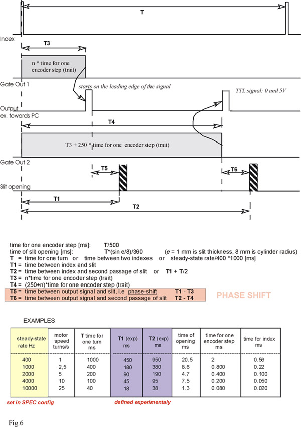
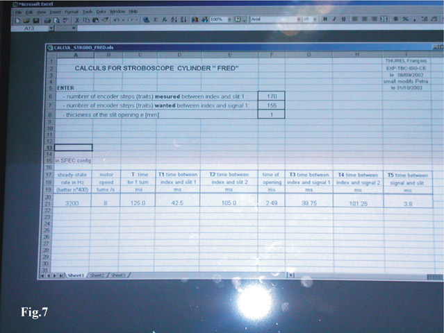
The exceed file CALCUL_STROBO.xls allows a quick calculations of the experimental parameters. It is installed on PC CHEOPS in the Control hutch, dir: F/strobo. Figure 7 shows an example of this file.
Synchronization macro "id19strobo" is saved on EUROPA in directory umacros. In any Spec session it can be called by 'udo id19strobo' command.
After 'strobosetup' command three questions are asked:
-
1) 1st delay (encoder steps): answer wanted value of phase shift in encoder steps;
2) 2nd delay: automatically proposed first value + 250;
3) server: id19/Vct6193_1 (if second VCT6 of 193 crate used for stroboscopy).
The synchronization starts with the parameters defined in strobosetup after 'strobostart' command. Note that the motor of the stroboscope should turn (in other Spec version that this one used for strobosetup) in order to deliver some signals to electronics.
Generally, what should be done before starting any strobo-game:
- stroboscope slit (make sure you know which slit/hole you are using) is aligned in the incident beam (restricted by primary and secondary slits in direction of the stroboscope slit), accurate slit for section topography (about 20 microns) behind the stroboscope aligned with respect to it
- Nitrogen tube connected on the stroboscope and gas ON
- VCT6 carte installed as 2nd VCT6 of 193 crate (for example), all modifications of the carte done, don't forget to stop/restart the crate when changing
- all cables connected: stroboscope motor and encoder cables, all LEMO cables between "Line Driver" and VCT6 carte, output cable from "Line Driver" towards the periodic phenomenon generator (check if it delivers to the sample a wanted perturbation)
- "Line Driver" powered (red led ON): power cable in the socket
- measure the time (for a given motor speed) between the index and the slit opening. Convert it into encoder step units.
- chose the adequate experimental parameters using CALCUL_STROBO.xls file (on CHEOPS: F/strobo) and modify accordingly the config of strobo motor (Spec HDIFFR)
-
run strobo motor during the time longer than the exposure time needed.
For example: mvr strobo 10 for config values step/deg. = 80000 (better if it is an integer multiple of 400, no limitation in its maximal value) and steady state rate = 400 (never set more than 8000!, if less than 400 the motor will turn very irregularly) motor will turn 2000 times, i.e. during 2000 seconds. As the slit time opening is about 20 ms (40 ms per turn) for this speed and 1 mm thick slit, the real exposure time (the time of the film illumination) is about 80 seconds. 'strobosetup' (do 'udo id19strobo' if needed) in different Spec version than the strobo-motor is running - 'strobostart; shopen; uct total-exposure-time-needed; shclose'
-
for further experiment shot modify the phase shift using
-
a) different speed of the motor,
b) different delay in strobosetup or
c) change the stroboscopic slit (manually), after this the new position index-slit opening should be measured
-
a) different speed of the motor,
partners


European Synchrotron Radiation Facility - 71, avenue des Martyrs, CS 40220, 38043 Grenoble Cedex 9, France.