Sample goniometer
Figure 1 shows a photograph of the sample goniometer. It comprises the rotational (theta, th), tilt (phi, chi) and translational (x, y, z) degrees of freedom. The sample stage can take loads up to 30 kg. For sample environment exceeding this weight, a counterweight system is available. All axes of rotation of the goniometer as well as the rotation axis of the spectrometer arm (twotheta, tth) are intersecting at one point. The whole unit is mounted with rails on a marble which allows to translate the whole goniometer, including the tth-rotation axis of the spectrometer arm perpendicular to the incident beam. This offers the flexibility to adapt the instrument to the incident-beam-deflection by the additional, horizontally focusing multi-layer element, which can be used to reduce the horizontal focus size to below 30µm.

Fig.1: The Huber 170mm x 170mm surface of the sample goniometer between the absorber wheel (left, incident beam side) and the spectrometer entrance slit and detector chamber (right).
The backscattering concept of the beamline imposes restrictions to the range of sample rotation theta (th) allowed by the white beam transfer line (crossing the goniometer) and by the spectrometer entrance. To overcome these restrictions, an additional sample rotation-stage (adth) can be installed, as shown in Fig. 2. At sample tilt angles phi and chi at zero, this new rotation axis is parallel to the standard theta-axis. However, depending on the sample environment this adth-stage offers only limited, manual stages to centre the sample with respect to the adth-axis.
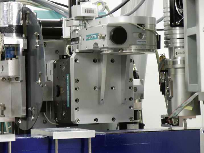
Fig.2: The optional, additional sample rotation stage adth mounted on the goniometer.
As visible in the Figures 1 and 2, the space on the sample goniometer allowing for sample environment is quite limited. The schematic drawings shown in Figures 3.a) and 3.b) show the available space and dimensions around the sample position.
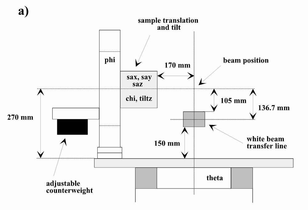
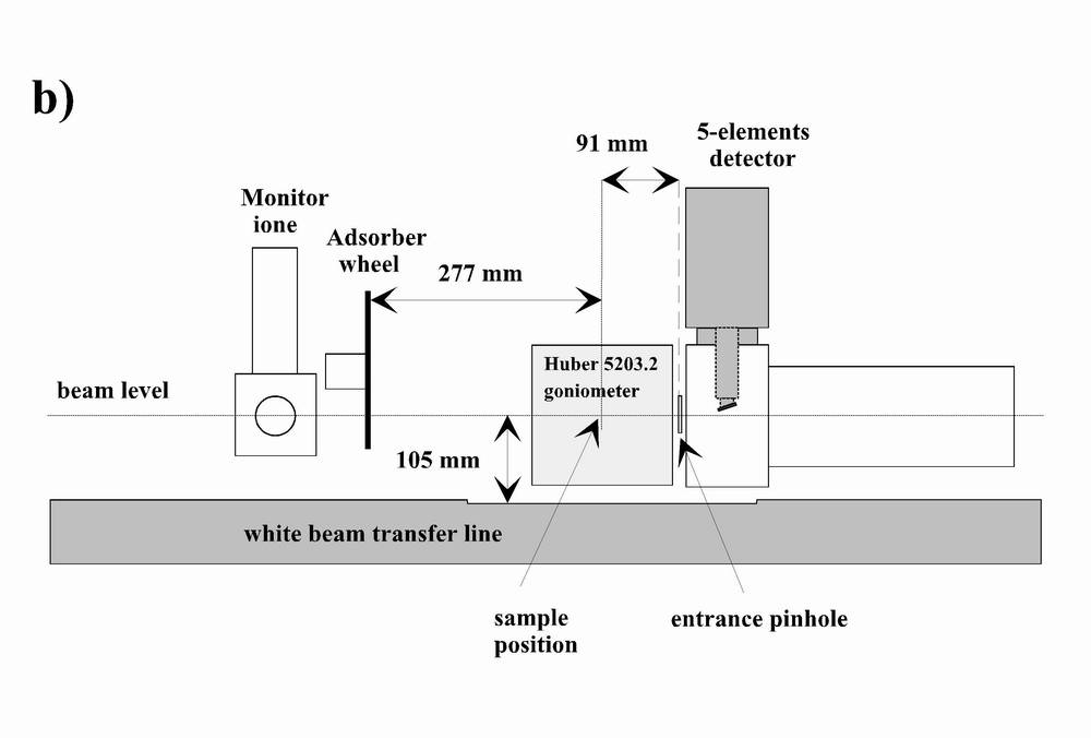
Fig.3: Schematic drawing of the elements and available spaces around the sample position. a) "Side view" along the incident monochromatic beam impinging on the sample position. b) "Front view" of the goniometer. The incident monochromatic beam impinges from the left onto the sample position.
partners


European Synchrotron Radiation Facility - 71, avenue des Martyrs, CS 40220, 38043 Grenoble Cedex 9, France.