Detectors
The diffracted x-ray intensity can be collected by a range of different detectors, from point detectors to high resolution 2D detectors depending on the problem studied. A special feature at ID09 is that if the beamline is run in stroboscopic mode a strong burst of x-ray pulses is recorded within a short time period of 100 ps, which cannot be resolved with most of the detectors. Therefore a photon counting mode is normally not feasible and detectors are run in an integrating mode (or current mode).
Characteristics of various detectors
| Detector | principle | Field of view | spacial resolution | time resolution | readout time | special requirements | |
|---|---|---|---|---|---|---|---|
| wire monitor | 0D | resistivity | - | 0.1 mm | - | - | - |
| photo diode | 0D | semiconductor | diam. 20 mm | none | 300 us | - | picoampermeter |
| GaAs | 0D | semiconductor | 1 x 0.4 mm | 1 x 0.4 mm | 60 ps | - | 3 GHz oscilloscope |
| Cyberstar | 0D | scintillator, photomultiplier | diam. 25 mm | 0.1 x 0.1 mm (slits) | 5 ns | - | fast oscilloscope |
| gas detector | 0D | gas discharge | diam. 100 mm | 3 mm (with mask) | appr. 100ns | - | preamplifier or boxcar |
| MarCCD | 2D | scintillator, fibre optics, CCD | diam. 133 mm | 100 mum | 0.1 sec | 8 sec | MAR system |
| streak camera | 1D | photocathode, electron optics, CCD | 12 x 0.2 mm | 0.1 mm | 800 fs | 1 s | optical delay line for photoswitches |
For the determination of the absolute time delay in between the x-ray pulse and the laser pulse a detector is used, that is sensitive to both kinds of radiation. It consists of a highly irradiated interdigitated GaAs photoconductor that is operated with a bias voltage. On a fast sampling oscilloscope (Tekronix) the trace of the signal can be recorded with a jitter about 20ps. The resolution of the system detector-oscilloscope has a time resolution of 60 ps and can thus even resolve the x-ray pulse in time.
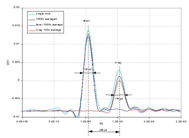 oscilloscope trace of the GaAs response (46 kB)
A Cyberstar scintillation counter will be used both for timing issues and for evaluating the I0 intensity that is actually impinging on the sample. This is possible by employing a lead plastic scintillator, that gives a time resolution of several nanoseconds. This value is enough to distinguish between different bunch pockets of the HF field.
The detector is placed directly after the sample slits 40 cm away from the sample position. The radiation hitting the detector is caused by air scattering and can be increased by introducing a scattering foil in the x-ray beam.
The principle of the two-dimensional detector is a thin scintillator plate (40 mm of Gd2O2S:Tb), that is connected to a fibre optic taber. The fibres demagnify the image by a factor of 2.7 and guide the scintillation light to a 3840 x3840 pixel CCD chip. The chip is cooled to a temperature of -80 C to reduce the dark current.
At ID09 the camera is equipped with a 1.6 mm thick beamstop, that is directly mounted on the beryllium entrance window to give an additional protection from the primary beam. The camera is mounted on a horizontal translation stage, that allows a variation of the sample-detector distance between approximately 50 and 600 mm.
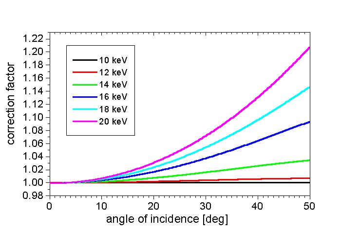
The efficiency of absorption of x-ray photons in the scintillator plate is optimized to allow the best point spread function as well as good detector efficiency.
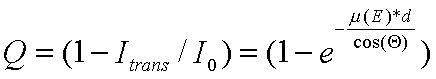
The absorption follows the equation:
That means that at higher angles of incidence the efficiency of the detector is higher (provided that the standard efficiency is not 100 %) and has to be corrected. This efficiency can be verified by illuminating the detector with an x-ray source of a well defined spatial emission like x-ray fluorescence. For the 40 mum thick Gd2O2S scintillator typical efficiency curves at various energies are depicted in the following graph:
partners


European Synchrotron Radiation Facility - 71, avenue des Martyrs, CS 40220, 38043 Grenoble Cedex 9, France.