- Home
- Users & Science
- Scientific Documentation
- ESRF Highlights
- ESRF Highlights 2010
- Accelerator and X-ray Source
Accelerator and X-ray Source
Throughout 2010, the Accelerator and Source Division has continued its efforts to ensure reliable operation as well as upgrading a number of systems. Some new developments have been carried out and many of these are described hereafter.
Beam parameters of the storage ring
Table 1 presents a summary of the characteristics of the storage ring electron beam.
 |
|
Table 1: Principal characteristics of the electron beam. |
Table 2 gives the main optic functions, electron beam sizes and divergences at various source points. For insertion device source points, the beta functions, dispersion, sizes and divergences are calculated in the middle of the straight section.
 |
|
Table 2: Beta functions, dispersion, rms beam size and divergence for the various source points. |
Two representative source points for each type of bending magnet (even or odd number) have been selected, corresponding to observation angles of 3 and 9 mrad from the extremity. The bending magnets are such that the magnetic field is 0.4 T and 0.85 T at the tangent point when the radiation is extracted at 3 and 9 mrad angles, respectively. Electron beam profiles are Gaussian and the size and divergence are presented in terms of rms quantities. The associated full width half maximum sizes and divergences are 2.35 times higher. Horizontal electron beam sizes and divergences are given for the uniform filling mode and apply to almost all filling patterns except for single bunch, for which a slightly larger size and divergence are attained because of the increased energy spread of the electron beam. Vertical electron beam sizes and divergences apply to 2 x 1/3 and 7/8+1 filling modes only. The vertical sizes and divergences are about 1.4 times larger in uniform filling mode (due to ion effects). To increase the lifetime of the stored beam, the vertical beam sizes and divergences are deliberately increased by about 3 in the 16 and 4 bunch filling patterns.
 |
|
Table 3: Current, lifetime, bunch length and energy spread for a selection of filling modes. |
The lifetime, bunch length and energy spread mainly depend on the filling pattern. These are given in Table 3 for a few representative patterns. Note that in both 16-bunch and 4-bunch filling patterns, the energy spread and bunch length decay with the current (the value indicated in the table corresponds to the maximum current). The bunch lengths are given for the usual radio frequency accelerating voltage of 9 MV (8 MV for 16-bunch and 4-bunch).
Summary of accelerator operation
In 2010, 701 shifts (5607 hours) of beam were initially scheduled. Of these 5607 hours, 5538 were effectively delivered (including 48.5 hours of refill). This represents a beam availability of 98.78%, which is an excellent figure, barely lower than last year's record of 99.04%. Dead time due to failures accounts for the remaining 1.22%. The number of failures was slightly higher compared to 2009 due to more repetitive and complicated failures originating from the storage ring radio-frequency system. However, The mean time between failures remains at a high level: 67.5 hours (75.8 hours in 2009). Table 4 presents an overview of operation in 2010.
 |
|
Table 4 : Overview of storage ring operation in 2010. |
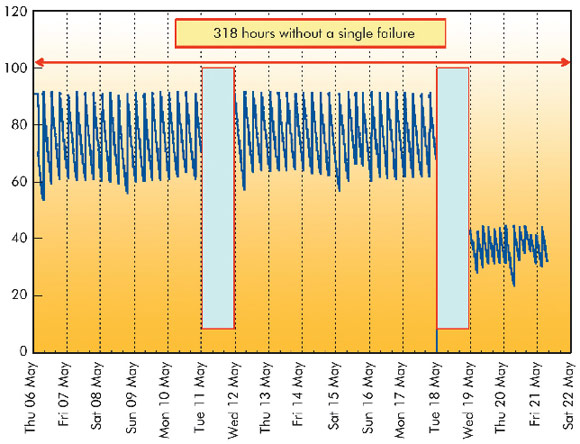
Eighteen long delivery periods (i.e. more than 100 hours) without a single interruption took place in 2010, in particular during the second run when the beam was delivered continuously for 13.25 days interrupted only by the two scheduled machine dedicated days (Figure 152).
 |
|
Fig. 152: An example of two weeks delivery without a single failure, interrupted only by 2 scheduled machine dedicated days. |
During the last months of the year, the beam has been regularly delivered with a very low vertical emittance in multibunch modes (see below).
In 2010, the shutdowns continued to be busy with the upgrade of ID straight sections, replacement of water flowmeters to increase the reliability whilst decreasing the maintenance costs.
Filling Patterns
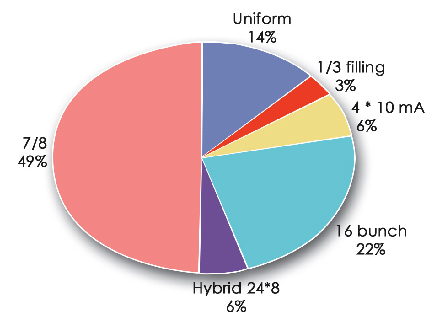
Figure 153 presents the distribution of filling modes delivered in 2010. There are no changes with respect to 2009. The filling mode labelled “7/8 + 1” remains the standard multibunch mode with almost 50% of the total shifts. Thanks to the vertical bunch-by-bunch feedback, the intensity of the single bunch present in the empty 1/8th gap has been increased from 2 mA to 4 mA compared to 2009.
 |
|
Fig. 153: Distribution of longitudinal filling modes in 2010. |
partners


European Synchrotron Radiation Facility - 71, avenue des Martyrs, CS 40220, 38043 Grenoble Cedex 9, France.