- Home
- Users & Science
- Scientific Documentation
- ESRF Highlights
- ESRF Highlights 2009
- Soft condensed matter
- Surface structure of sterically-stabilised ferrofluids
Surface structure of sterically-stabilised ferrofluids
In ferrofluids [1] magnetic nanoparticles are conventionally stabilised by a single or double layer of surface-active molecules (surfactants) [2]. Steric repulsion between surfactant shells assisted by Brownian motion prevents particle coagulation due to attractive dipole-dipole interaction. If no external magnetic field is applied, the particles are randomly distributed and the ferrofluid behaves like a superparamagnetic gas. But even relatively small fields break the force balance, which leads to pronounced spatial correlations between the particles observed in the bulk ferrofluid in the form of ordered chains, columns, and pseudocrystalline structures. These findings give ferrofluids a bright perspective for applications in nanotechnology.
Field-induced ferrofluid ordering at the interface with another material looks particularly interesting because it can be applied to the production of nano-structured magnetic surfaces or multilayers. Employing a ferrofluid-solid interface is one of the most straightforward ways to realise this idea, however, in this case the ordered part of ferrofluids adjacent to the interface [3] is hidden behind a substrate and its practical exploitation requires some non-trivial technological tricks.
The present study focuses on an easily accessible interface of ferrofluids with gas, i.e. a “free” ferrofluid surface. Besides its promising practical applications, it has a general scientific interest. In particular, studying field-induced particle ordering in this system brings us new information about famous Rosensweig instability (RI) observed as a system of standing waves appearing on the ferrofluids surface as soon as a critical value of magnetic field Hc is surpassed [1].
Magnetite nano-particles were fabricated by chemical deposition and dispersed either in water or in oil (tetradecane). Mean size of the particles was about 100 Å with 30% dispersion. A double layer of sodium oleate and a single layer of oleic acid were used to stabilise the particles in water-based and oil-based samples respectively. X-ray reflectivity (XR) and grazing incidence diffraction (GID) measurements were performed at beamline ID10B, which is especially designed for the scattering on liquid surfaces.
 |
|
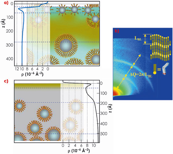
Fig. 73: Ferrofluid surface structure. a) Water ferrofluid, dark clouds schematically show agglomeration of sodium oleate molecules. Horizontal lines separate main structural sub-layers. Experimentally determined scattering length density (SLD) in-depth distribution is superimposed on the left side of the sketch and scaled appropriately. b) Small-angle GID pattern from the water ferrofluid revealing surface organisation of the oleic acid in to multilamellar structures. c) Sketch of the oil ferrofluid with corresponding SLD profile. |
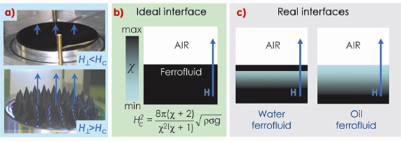
Simultaneous treatment of the XR and GID experimental data allows a considerably detailed reconstruction of the gas-ferrofluid interfaces. The interfacial structure differs drastically from the homogeneous state and depends on the liquid carrier and type of surfactant. Schematic arrangement of the ferrofluid surface layer for water and oil samples are shown in Figure 73. The surface layer of water-based ferrofluid has complicated structures (Figure 73a) provided by the excess of free surfactant. It is partially organised into multilamellar sheets, which can be deduced from the characteristic diffraction patterns (Figure 73b). This seems to be unavoidable in the case of polydisperse nano-particles stabilised with a double layer of amphiphilic molecules. In oil-based ferrofluid (Figure 73c), the main feature is the gradient of the particles concentration C ranging from C = 0 at depth z = 50-100 Å (pure oil) to the nominal C = 13% at z = 500 Å. The topmost layer is the Gibbs layer of oleic acid on tetradecane. These structures self-replicate several times after their gentle removal from the sample surface and qualitatively do not depend on the particle concentration. For this reason, such a top “coating” can appear as an intrinsic feature of sterically-stabilised ferrofluids. It must govern to a greater extent the value of the surface tension and local magnetic susceptibility and, therefore, determine such RI parameters as the critical field Hc and the period of the standing wave (Figure 74). The extent of the particle depletion in the ferrofluids surface layer should also define the rate of the RI undulation growth with increasing field. Indeed, we have observed microscopic evolution of the surface topology already at H = 0.5 Hc, i.e. in fields much smaller than predicted by the RI theory for an ideal sharp interface.
 |
|
Fig. 74: a) Photos of free ferrofluid surface in sub-critical (top) and super-critical (bottom) magnetic field. b) Colour-coded distribution of magnetic susceptibility |
References
[1] R.E. Rosensweig, Ferrohydrodynamics, Cambridge (1985).
[2] L. Shen et al., Langmuir 15, 447-453 (1999).
[3] A. Vorobiev et al., Phys. Rev. Lett. 93, 267203 (2004).
Principal publication and authors
A. Vorobiev (a), G. Gordeev (b), O. Konovalov (a), and D. Orlova (b), Phys. Rev. E 79, 031403 (2009).
(a) ESRF
(b) Petersburg Nuclear Physics Institute (Russia)
partners


European Synchrotron Radiation Facility - 71, avenue des Martyrs, CS 40220, 38043 Grenoble Cedex 9, France.