Workflows for automated data collection
Workflows have been developed to allow the full characterisation and data collection from a large number of crystals with no user intervention. Multiple crystals are selected in MXCuBE which takes care of the mounting / optical centring / unmounting of each sample. Once a sample is mounted and optically centred an MXPress workflow is launched. This workflow first uses a mesh scan and a line scan to centre the best part of the crystal to the X-ray beam. They are available on all MX beamlines of ESRF. The process is fully described in these publications:
Svensson, O., Monaco, S., Popov, A. N., Nurizzo, D. & Bowler, M. W. (2015). Fully automatic characterization and data collection from crystals of biological macromolecules, Acta Cryst. D71, 1757-1767
Svensson, O., Gilski, M., Nurizzo, D. & Bowler, M. W. (2018). Multi-position data collection and dynamic beam sizing: recent improvements to the automatic data-collection algorithms on MASSIF-1, Acta Cryst. D74, 433-440
Please cite if you found MASSIF-1 or X-ray centring useful in screening, data collection or structure solution.
Fogh, R. H., Keller, P., Flensburg, C., Vonrhein, C., Paciorek, W., Carter, L. & Bricogne, G. (2026). Automated workflows for strategy computation and data collection at synchrotron beamlines Acta Cryst. D82. https://doi.org/10.1107/S2059798326001920
Please cite if you used the Global Phasing workflows.
Contact Matthew Bowler for help.
Mail-in services are proposed on MASSIF-1 using these workflows that will have their greatest impact on the initial stages of challenging projects (large numbers of crystals are evaluated but no data is collected) and for established projects where large numbers of data sets are collected (functional mutants and ligand binding studies / Industrial clients). The following experiment types can be selected in the diffraction plan in the Data Portal:
Definition of the workflows
MXPressE – Crystals automatically centred to the beam using optical loop centring followed by X-ray centring – no restrictions on crystal size relative to the loop. Data collection based on eEDNA strategies using crystals measurements and real time flux meaning that the best possible data are collected from each sample. Results available in ISPyB as they arrive. Autoprocessing of data. Can be customised using the diffraction plan (see below).
MXPress Global Phasing Basic - As above but after EDNA characterisation the resolution and dose budget are passed to the Global Phasing workflow that then calculates an optimised strategy - for high symmetry space groups this will usually mean a single sweep, but can involve kappa reorientation. For lower symmetry two sweeps can be collected. After the movement of the kappa goniometer a second round of X-ray centring is triggered. Sweeps will be merged automatically and displayed in the data portal. This is the default workflow for samples.
MXPress Global Phasing Full - as above but a complex multi-sweep strategy will be launched. The best option for maximum completeness, especially at low symmetry. Sweeps will be merged automatically and displayed in the data portal.
MXPress Global Phasing minimal - as for the basic strategy but a reduced osscilation range compared to Basic.
MXPressE SAD – as above but eEDNA strategies used that are optimised for SAD data collection - strategy optimised for high redundancy (360°) with the resolution set to where the Rmerge between Bijvoet pairs is 5%. Autoprocessing of data. Can be customised using the diffraction plan (see below).
MXPressP - performs a pseudo-helical data collection on positions determined within a crystal. Can be customised using the diffraction plan (see below) default number of positions is 5. Wedges will be merged automatically and displayed in the data portal.
MXPressP_SAD - performs a pseudo-helical data collection on positions determined within a crystal but for an optimised SAD strategy. Can be customised using the diffraction plan (see below)
MXPressF - for fast characterisation of robust crystals. Instead of a full EDNA/BEST characterisation the resolution and exposure time to reach the Garman limit (reduction in diffraction power to ~70%) is estimated from the best image in the mesh scan. A default 180° with 0.1°oscillations is collected - this can be changed using the required axis range in the diffraction plan to any required rotation range, with the exposure time per image being adjusted accordingly.
MXScore – as for MXPressE but data collection not included. Results available in ISPyB showing full quality assessment of crystals. Results available in ISPyB as they arrive.
MXPressI – Crystals automatically centred to the beam using optical loop centring followed by X-ray centring – no restrictions on crystal size relative to the loop. Data collection 180° with 0.2° oscillations starting from phi angle and the resolution determined by the eEDNA strategy. Results available in ISPyB as they arrive. Autoprocessing of data.
MXPressO – Crystals automatically centred to the beam using optical loop centring followed by X-ray centring – no restrictions on crystal size relative to the loop. Data collection 180° with 0.2° oscillations at 2 Å resolution or the pre-observed resolution. Results available in ISPyB as they arrive. Autoprocessing of data.
MXPressM - performs a high dose mesh scan over the widest orientation of sample support with no data collection or centring - designed for screening initial hits to identify protein crystals and provide initial indications of diffraction quality.
NEW: Any of these services can be used for multiple crystals in loops by entering a number of positions in the diffraction plan (see below).
The service has no restrictions on the type of loops or crystal size but we do require that all samples are SPINE standard and that barcodes are uploaded to ISPyB in order to provide redundancy in sample identification as users will not accompany their samples.
Graphical overview of the MXPressE/O process
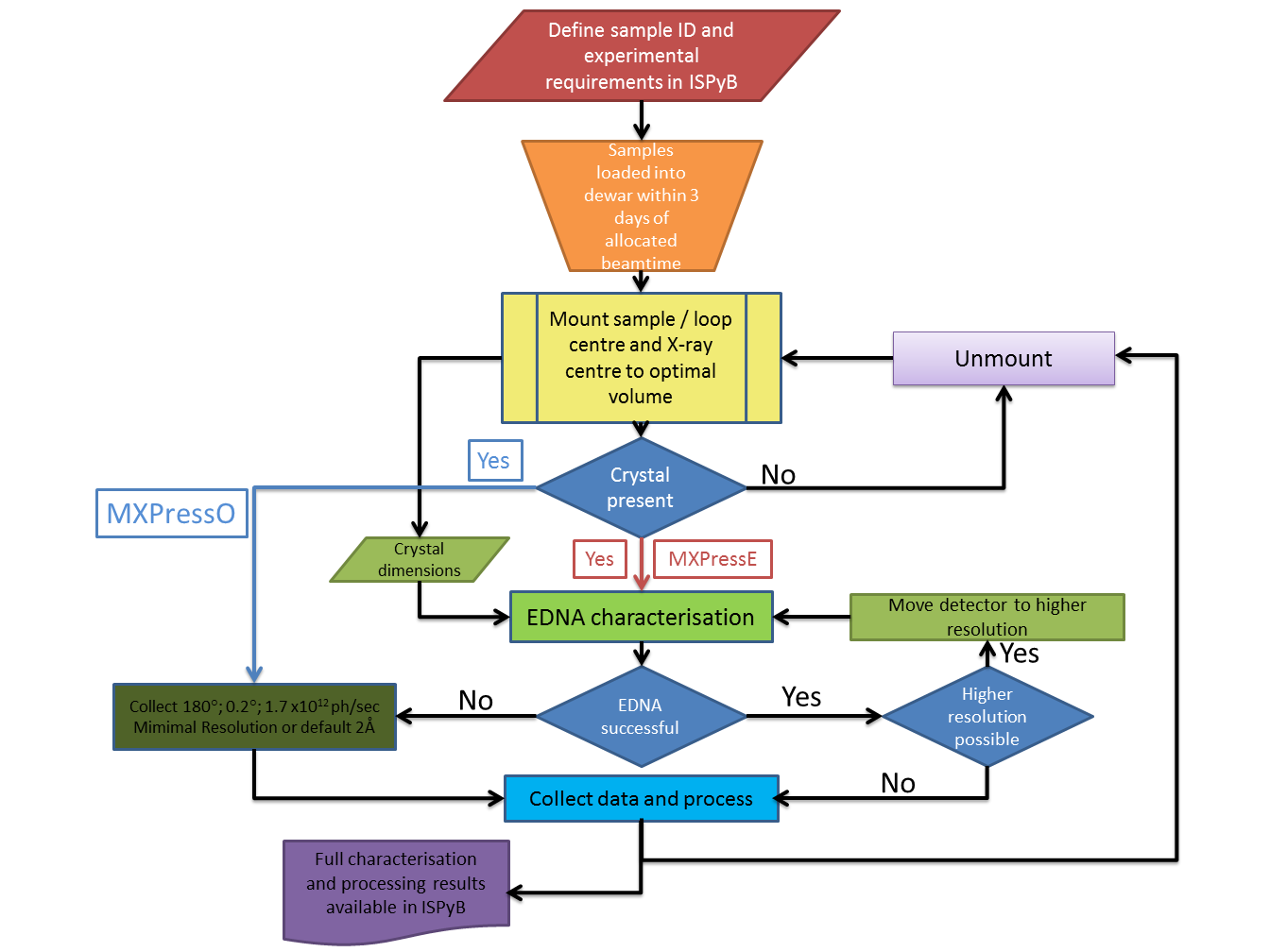
Each of the major steps is described in detail below.
1. Automatic determination of mesh parameters
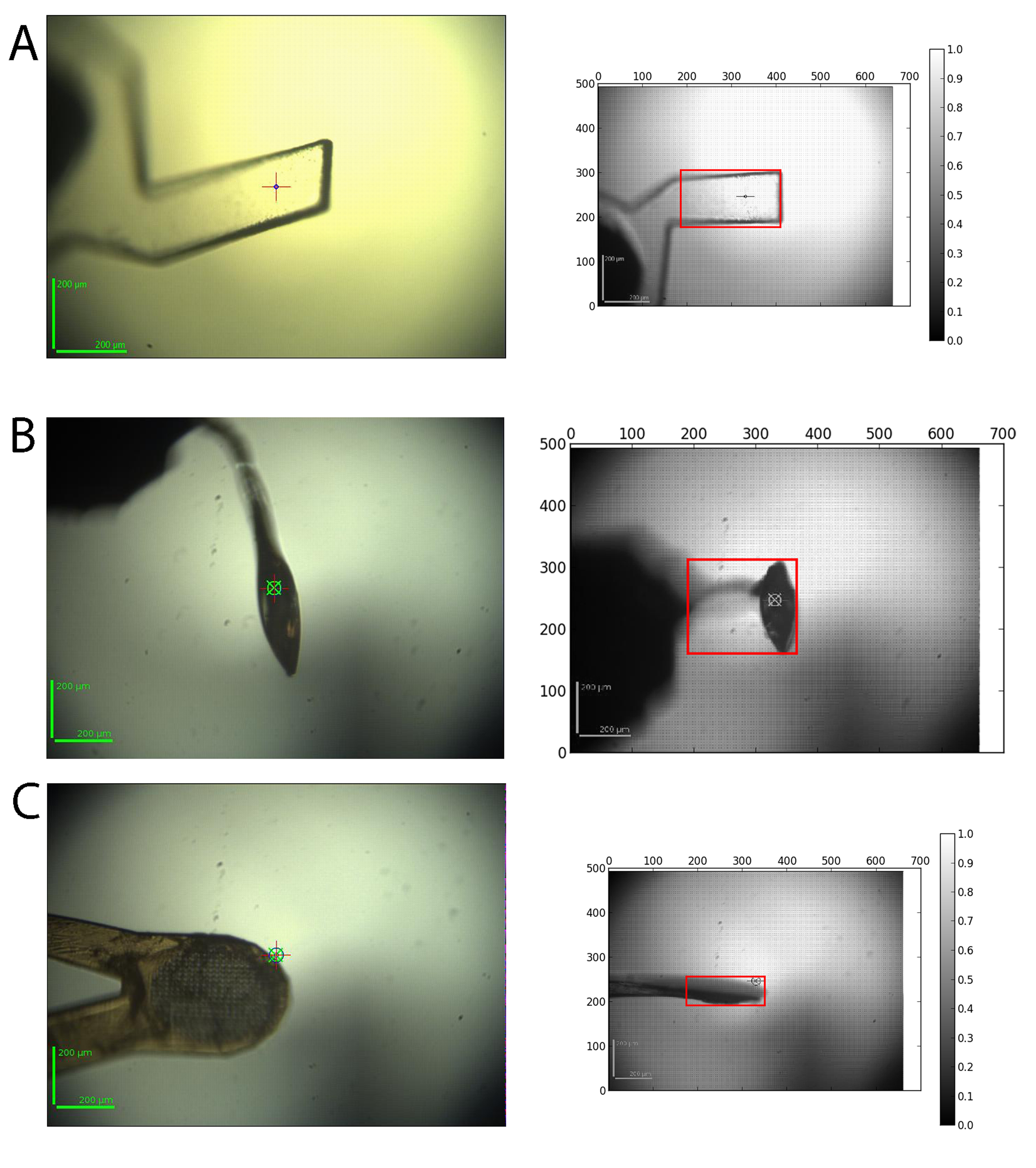
Crystals vary widely in their morphology and can be mounted in a wide variety of supports. The input for the automatic determination of the mesh scan area is a series of 12 images acquired from the on-line video microscope where the goniometer rotation axis is rotated by 30° between each image. For each image a background subtraction, Gaussian smoothing and the application of a threshold to find the contour is performed. The contours of all 12 images are then analysed and the images corresponding to the minimum and maximum vertical sample support size are selected. The corresponding rotation angle at which the mesh scan should be carried out and the size of the grid are returned as results. A snapshot of the area is also taken to ensure the loop was covered in the mesh is available in ISPyB:
2. X-ray centring
The evaluation of the sample involves scanning the whole face of the crystal in order to define the best diffraction volumes. Images from the scans are analysed for signal above background and intensity distribution against resolution thereby eliminating false positives from ice rings, a comon problem when only analysing total signal. The centre of mass of the best positions is then determined and the sample rotated 90° and a mesh scan performed using the same analysis and centre of mass calculation. We have found this method to robustly centre crystals down to 10 microns. The scan provides information on the variability of diffraction within each crystal as well as its dimensions.
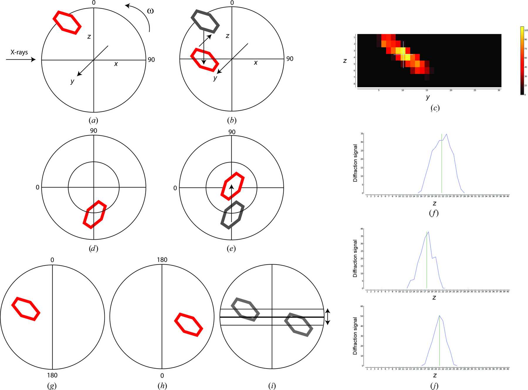
(A). Once optical centring is completed a crystal in a loop (red) will rotate about the goniometer centre of rotation (w). A mesh scan determines the horizontal and vertical translations required to bring the crystal to the centre of rotation at this angle using the goniometer horizontal translation and the centring table motors (B and C). Rotating the spindle by 90° (D) and performing a vertical scan determines the final movement of the centring table motors required to place the optimum diffraction volume of the crystal on the centre of rotation of the spindle (E and F).This example shows values of omega of 0° and 90° for convenience, arbitrary starting values of omega can be used.
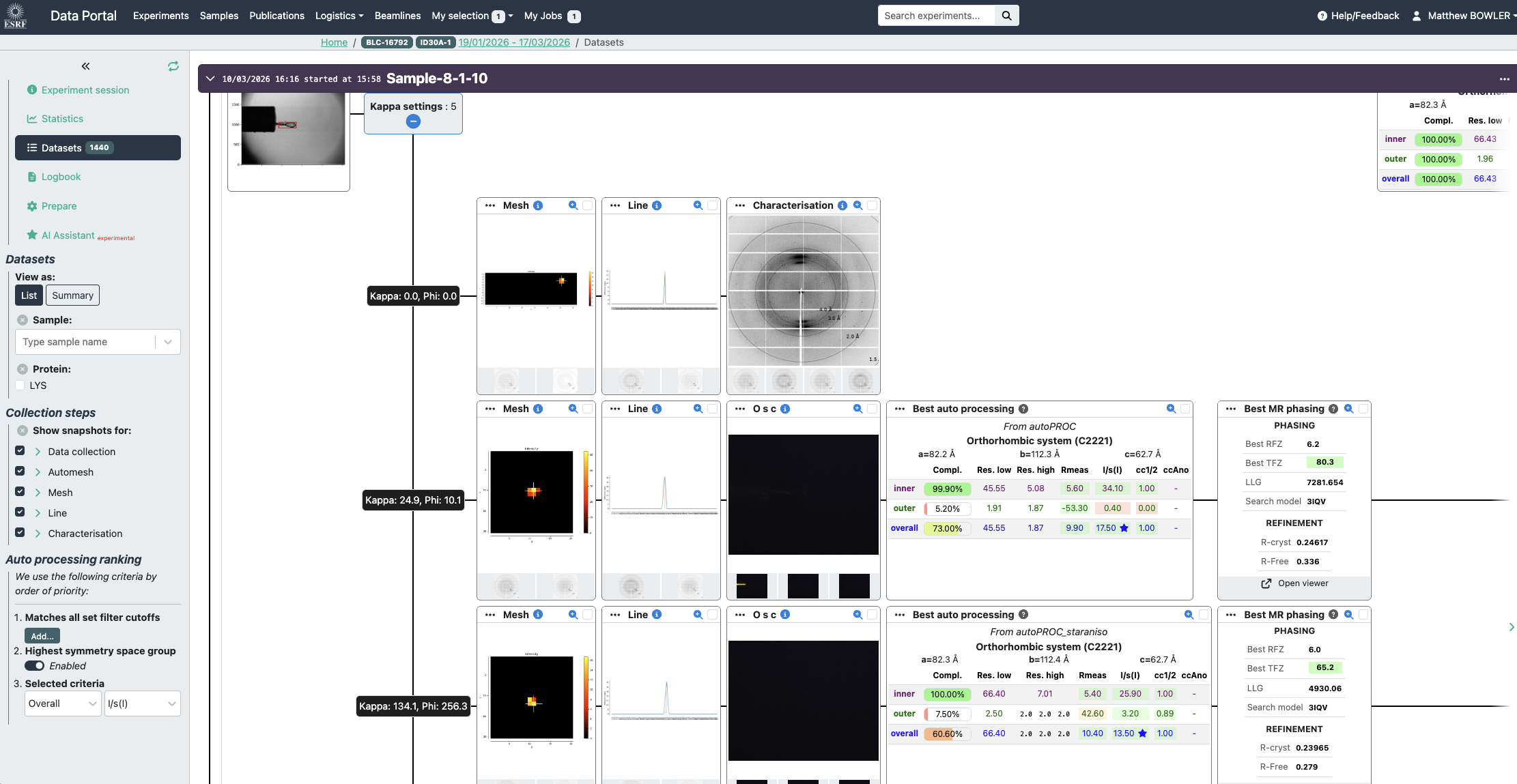
All results are available in the data portal and a summary can be viewed of the scans, characterisation and automated data processing:
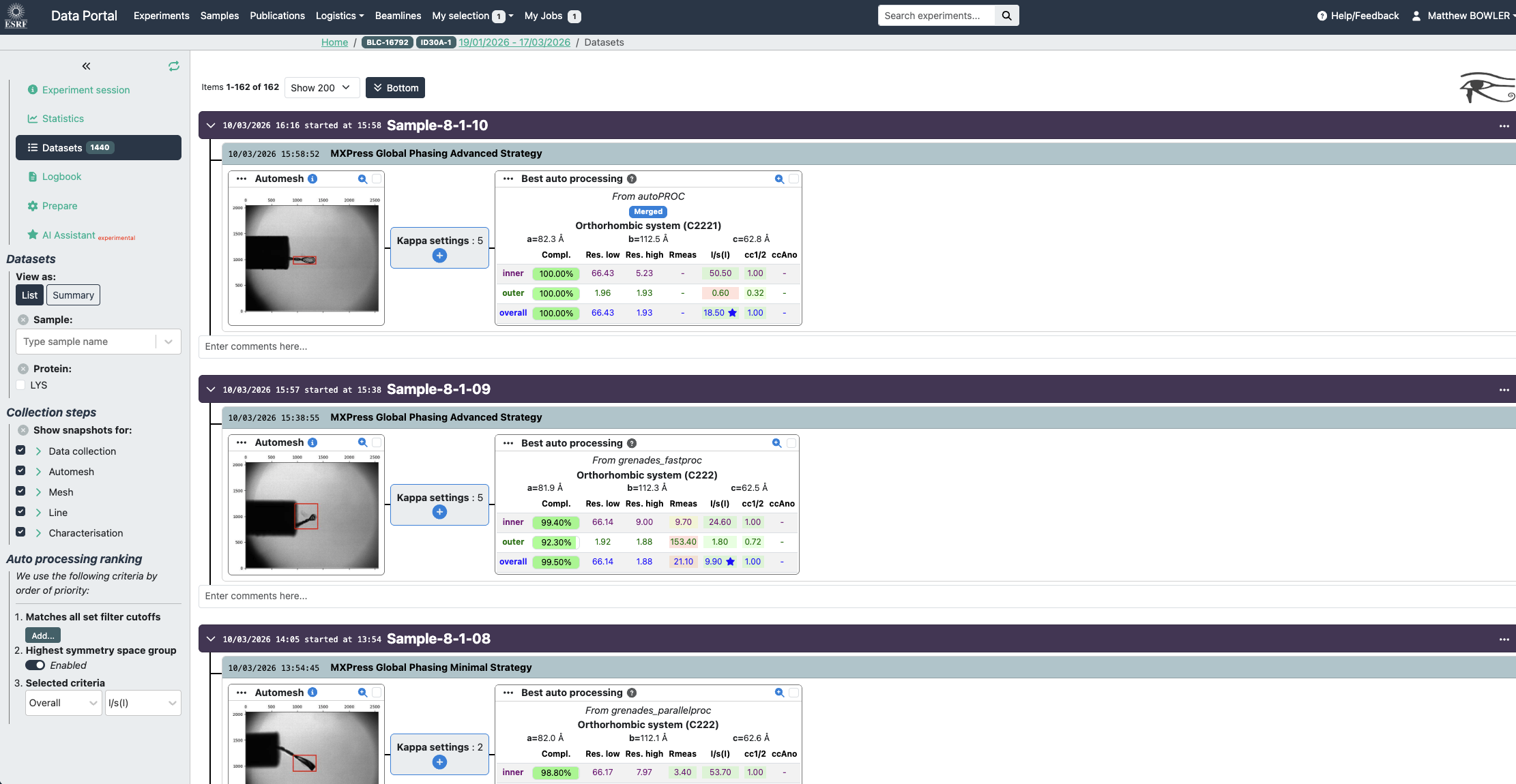
Example data collections in the Data Portal. Experiment conditions are summarised as well as snapshots of the crystal (red box defines scan area). Diffraction maps of the crystal, first a mesh scan locates the best position in 1 dimension, the sample is then rotated 90° and a line scan is performed (line chart). The centring table of the goniometer is then moved to centre the optimal location to the X-ray beam. In this case a MXPress Global Phasing Full strategy is shown with the sweeps merged data set displayed. Full experiment details can be viewed by clicking the 'kappa settings' button. (see below).
Users are also able to upload a considerable amount of information about samples if required, this is not essential. For example if the resolution that has already been observed is uploaded the workflow will use this resolution to perform mesh scans. See below for a table of variables that can be uploaded.
Timings for automated workflows on MASSIF-1 (Times are from the first 1500 samples run in 2015) :
| Step | Mesh scan (s) | EDNA characterization (s) | EDNA data collection (s) | Default data collection (s) | Workflow total time (s) |
|---|---|---|---|---|---|
| Mean | 101 | 25 | 108 | 113 | 440 |
| Mode | 62 | 9 | 72 | 113 | 395 |
| Median | 85 | 22 | 95 | 112 | 444 |
| Maximum | 299 | 138 | 316 | 138 | 993 |
| Minimum | 35 | 5 | 14 | 109 | 85 |
| N | 1240 | 1147 | 552 | 551 | 1240 |
Diffraction plan entries that can be defined in the Data Portal by users and used by the automatic workflows.
The diffraction plan holds all the information needed on a sample and can be described in the Data Portal. Essential entries in the diffraction plan are the sample acronym and a unique sample name as well as the puck barcode.
Additional information can be added to tailor the experiment performed for each sample:
| Diffraction-plan entry | Definition | Default value |
|---|---|---|
| Protein acronym | Defines the protein that is registed with the ESRF safety group (SMIS) | Required field |
| Sample name | User-defined unique identifier | Required field |
| Pin barcode | Barcode identifier | None |
| Experiment type | Define MXPressE/O/SAD/Score/M/P/P_SAD/F | MXPress Global Phasing Basic |
| Crystal form | If present (from an associated PDB) used for strategy calculation and autoprocessing (except some Grenades jobs) | None |
| Aimed resolution | Resolution that the detector will be set to for mesh scans, characterization images and default data collection | 2.0 Å |
| Required resolution | Threshold resolution; samples below the cutoff will not be collected | None |
| Radiation-sensitivity | BEST input in the case of highly radiation-sensitive crystals (0.5–2.0 - low to high sensitivity) | 1 |
| Required completeness | % of Completeness required (value between1 and100) | 99% |
| Required multiplicity | — | 4 |
| No. of positions | For multiple crystals on your support or for helical data collection (MXPressP) | 1 (5 for MXPressP and P_SAD) |
| Beam diameter | Select appropriate beam size for crystals (if blank will be dynamically adapted to crystal size) - value in µm | 30 µm |
| Forced Space Group | Select space group for strategy calculation and autoprocessing if cell not known or no PDB | None |
| Total rotation angle | Select required rotation range for data collection |
MXPressE - minimum required MXPressE_SAD - 360° MXPressO - 180° MXPressF - 180° MXPressP - 180°/positions MXPressP_SAD - 360°/positions |
| Observed resolution & Comments are two fields that are not used by our Worklows, but are only a help to the users | ||
The diffraction plan interface in the data portal:
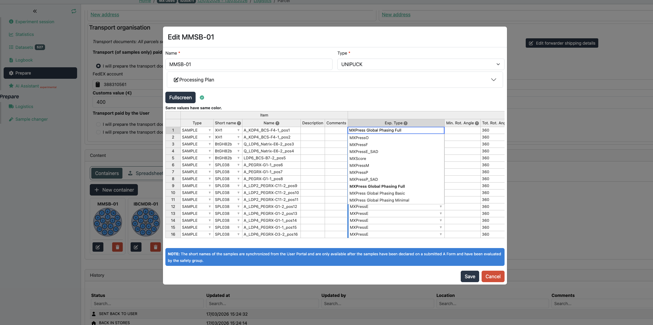
The create puck interface in ISPyB is where information about each sample is uploaded. The example above shows a mixture of samples where information has been added.
The only compulsory fields are sample acronym and name and the puck barcode (in the 'Puck:' field above).
All other fields are optional and have sensible default values if no information is provided (see table above). The experiment type field is important as if an experiment other than MXPressE is required (such as MXPressE_SAD, SCORE or MXPressO, click here for more details) it must be entered here. The beamsize is an option to select the diameter of the beam in microns - this should be appropriate to your crystals. All other fields contribute to the strategy for data collection where the space group can be forced, resolution, multiplicity etc can be chosen.
partners


European Synchrotron Radiation Facility - 71, avenue des Martyrs, CS 40220, 38043 Grenoble Cedex 9, France.